Transmitter. Continued
Description
This section is from the book "Amateur Work Magazine Vol4". Also available from Amazon: Amateur Work.
Transmitter. Continued
If, however, the elevated conductor be not directly connected to the earth, but be connected to it through an inductance coil, both theory and practice show that its electrical vibrations correspond to the transverse vibrations of a heavily damped stretched string with a mass attached to its center.
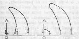
Fig. 6.
The effect of the load at the center of the stretched string and of the inductance at the base of the vertical wire is to increase the persistency of the vibrations, to minimize the importance of the harmonics and to lower the frequency of the fundamental.
It might, therefore, seem that in order to cause the vertical oscillator in question to radiate a persistent train of simple harmonic waves of a predetermined frequency, it would be sufficient to charge the vertical wire to a high potential and permit it to discharge to earth through an inductance coil of suitable dimensions.
This, indeed, was the plan adopted in the first crude attempts to produce a selective system of wireless telegraphy. This method necessitates the use of waves of much lower frequency than that normally produced by natural vibrations of the vertical wire per se.
The degree of persistency of oscillations so obtained, however, is not as great as is required in practice. Such persistency as is obtained is gained at the expense of the amplitude of the current oscillator, the latter being caetiris paribus less for low than for high frequencies. Moreover, the spark in the vertical oscillator which normally dissipates an undue amount of the energy of the oscillations, has its resistance enhanced by the reduction of the amplitude of the current oscillations due to the presence of the inductance coil.
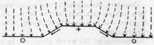
Fig. 7.
The latter difficulty may in a measure be overcome at the expense of any increase of the energy supplied to the oscillator, by shunting the spark gap by a condenser of large capacity. The discharge of the condenser across the spark gap increases the current through the spark and thereby reduces its resistance and damping effect upon the oscillations. The damping effect of the radiation still remains and the persistency is still too much limited for practical purposes.
So far we have considered only the natural oscillations of the vertical oscillator which are produced by charging the elevated conductor to a high potential and then permitting it to discharge to earth. When, however, a high degree of persistency, a pure sine wave and a great amplitude of oscillation are desired, the spark gap is removed from the vertical oscillating circuit and a simple harmonic electro-motive force is impressed upon the vertical oscillator in its place. The resulting vibrations in the vertical oscillator are then forced simple harmonic vibrations. In order that they may be of great amplitude, the frequency of the impressed force is made to correspond to the fundamental of the vertical oscillator or to one of its harmonics, in which cases the reactance of the vertical oscillator is nil.
A simple arrangement for producing forced, simple harmonic vibrations in the vertical oscillator is shown in Fig. 9 in which G is an alternating-current generator, K is a key, P shows the connection to the terminals of the primary of a spark coil, C is a condenser, L is an inductance, I and I2 are the primary and secondary coils of a high-frequency transformer, V is the vertical wire and E is the earth.
There is a variety of ways in which substantially the same results may be accomplished, but there is not space in this article to consider more than one arrangement. **********
Concerning the arrangement illustrated in Fig. 9, there is much of detail which requires attention in order that the apparatus shall satisfactorily fulfil the requirements of radiating a persistent train of simple harmonic waves. For instance, if a dialetric having considerable electrostatic hysteresis be employed in the condenser, a surprisingly large amount of energy will be dissipated in this dialetric. The magnitude of this loss is due to the fact that the energy dissipated increases both the potential difference employed at the terminals of the condenser and also with the frequency. Since the potential difference employed at the terminals of the condenser amounting to 50,000 volts and oscillations having frequencies of 5,000,000 are not unusual in wireless telegraphy, it is easy to see that the losses in the dialetric of condensers employed in the usual power or lighting circuits.
Moreover, the specific inductive capacity of most die-letrics is a function of the density of the displacement current in the dieletric, and when such dieletrics are employed in the condenser in an oscillating circuit, the resulting oscillations are not simple harmonic in form and are not isochronous throughout the train.
Air condensers should therefore be used in wireless telegraphy to the exclusion of any other type pending the publication of the results of certain investigations which are being conducted with the view of supplying a dieletric of high dieletric strength and constant specific capacity.
The coils used in wireless telegraphy should not have iron cores except the iron be very finely comminuted and imbedded in a non-hygroscopio dieletric matrix. It has even been found by the author that coils wound on a wooden cylinder do not operate satisfactorily when used in the oscillating circuits of wireless telegraphy. The coils for this purpose are

Fig. 8.
best constructed by winding a few turns of bare copper wire in a single layer on a skeleton frame made of ebonite, care being taken to separate the turns by such an amount that the sum of the air spaces between the wires of the turns is equal to or slightly greater than the sparking distance in air corresponding to the greatest potential difference liable to occur at the terminals of the coil when the apparatus is in operation.
An isolated circuit of the type shown in Fig. 9, may be made to give extremely persistent simple harmonic oscillations, but if it be given a large coefficient of muinductance with another oscillator of relatively low persistency, such as the vertical oscillator VI2 E of the arrangement shown in Fig. 9, two things happen. In the first place the two oscillations of the circuit are in general no longer simple harmonic, but are broken up into two simple harmonic oscillations of different frequencies, and in the second place the persistency is greatly reduced.
To overcome this difficulty it is necessary either to make the magnetic leakage of the high frequency transformer, connecting the local oscillating circuit with the vertical oscillator, unusually large, or else to the local oscillating circuit an inductance coil M, with sufficient inductance to swamp by its effect the reaction from the secondary circuit.
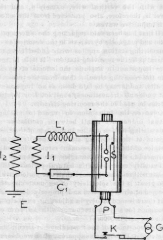
Fig. 9.
When intense radiation is desired, it is necessary to make the capacity S of the condenser C1 in the local oscillating circuit large compared to S1, the apparent capacity of the elevated conductor per se. for the frequency employed.
Continue to:
My Books

