


Vibrator For Induction Coils
Description
This section is from the book "Amateur Work Magazine Vol4". Also available from Amazon: Amateur Work.
Vibrator For Induction Coils
H. C Burnham
The difficulties encountered with vibrators of induction coils are, that the contacts are liable to fuse or burn, and that the core is not fully magnetized so that the full power of the coil is not produced in the sparking. To overcome the first we must have a spring that upon magnetizing the core will break the circuit quickly. To overcome the latter we must have a vibrator that will work evenly and be slow enough to allow the core and primary to become fully energized, thus securing the best results in the spark of the secondary.
The vibrator here described will accomplish these results. To make it procure a strip of spring brass, A, 3 in. long by 1/4 in. wide. (It must be very springy and so that it will bend with a very slight pull.) At one end measure off | in. and bend to a right angle. Drill two holes in this short bend for screws ; at the other end, 1/4 in. down and in the center, drill a hole 3-16 in. in diameter.
Next, get from a hardware store a small brass machine screw 1/8 in. diameter, with a nut to fit. Solder this nut c over the hole just mentioned. Also obtain a round piece of soft gray iron, D, 3/4 in. in diameter, saw off a piece 1/4 in. thick and rivet it onto the spring A so as to be exactly opposite the end of the core and directly face to face with it.
Next, get a piece of cherry H, 2$ in. wide and of the same thickness as the end of the core which projects from the end of the coil. On my coil this is 1/2 in. Screw this to the brass so that it fits snugly against the end of the coil, and is 1/8 in. from the outer edge of the coil head, as shown in the illustration.
Procure a piece of very heavy spring brass c 1 5/8 in. long and 1/4 in. wide. Drill two holes in this piece for the screws J J. Screw this piece to the block II bo that it is long enough to go about 1/8 in. beyond where the screw B strikes it. One inch from the outer end solder a piece of sheet platinum about 3-16 in. square in the center of the point of contact with the spring F. Now take a piece of brass 1 1/2 in. long by £ in. wide and 1-16 in. thick. Drill two holes for the screws L L. At the other end drill a hole 3-16 in. diameter and 3-16 in. from the end. Get another brass machine screw 1-8 in. wire, with nut to match. Procure a piece of No. 12 platinum wire 1-8 in. long. Solder this totheendof the machine screw, then solder the nut to F so that it centers on the 3-16 in. hole previously drilled near the end. Mount this piece of brass so that the platinum tipped screw E centers on the piece of sheet platinum soldered on to G.
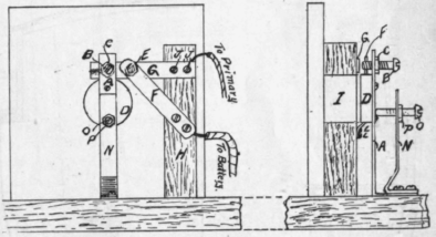
Take another piece of brass 2 in. long by 1/4 in. wide and 1-16 in. thick and a brass machine screw 1-8 in. wire with a nut to match. Drill a 3-16 in. hole 1/4 in. from the end and solder this nut p over it. Bend this piece so that the screw-hole will stand out about 1/4 in. from the piece A. Mount this piece N with the same screws that hold the piece A.
Now for the adjustment. Mount the spring A so that the iron disk D is about 3-64 in. from the core I and is directly line with it. Mount the strip of cherry so that the screw B hits the spring G about 1/4 in. from the end. The strip F isto be mounted on the. piece of cherry so that the screw B hits the spring G about 1/4 in. from the end. The strip Fis to be mounted on the piece of cherry so that the platinum tipped screw centers on the piece of sheet platinum. See that the spring G bears strongly against the screw E. Adjust the screw B so that just before the iron disk D touches the core 7, the screw B will strike the heavy spring G. Adjust the piece N with the screw so that the weak spring A can only fly 3-64 in. back from the core I.
Now for the connections. Under the screws JJ solder a wire and connect it with one of the primary wires. Solder a wire to the piece F and run it to the binding post for the battery.
Continue to:


My Books

