A High Speed Launch. Part 4
Description
This section is from the book "Amateur Work Magazine Vol5". Also available from Amazon: Amateur Work.
A High Speed Launch. Part 4
The coaming is of 1/4 in. oak and stands 3 in, high above the deck and is curved up at the forward end, as shown. It is fitted and supported by small blocks, as shown in Fig. 11. At the after end it runs out on to the deck and is curved off as in Fig. 5. The forward end of the coaming is sloped forward somewhat to shed the water and also to enable it to be more easily fitted; at the point a small block is fitted on the inside to join the two sides together.
The skeg is shaped as in Fig. 5, from 1 1/2 in pine, and bored with a | in. hole for the shaft, to match that already made in the hull. It is fastened through from the inside and must be carefully lined with the center line of the boat. A very thin lead pipe is now to be fitted inside of the shaft hole extending from the after end of the skeg to the inside of the boat.
The inside of the hole is well covered with paint before inserting the pipe, which is then turned over on end and hammered down close upon the wood, thus making a watertight joint all through.
The rudder is of 1/2 in. stock of the shape shown and is 16 in. long; the part forward of the forward edge of the stock being 2 1/2 in; the straight stock is 3 in. wide. A cleat is fastened along the lower edge to prevent its warping. The rudder is swung upon either the usual rudder braces or upon brass screw eyes. In the latter case four eyes are used and a brass rod is passed through, the lower eye taking the weight of the rudder. By so fitting the eyes that those on the rudder just fit between those on the hull, the rudder is held exactly in place. For a tiller a light brass casting may be made, or a wooden tiller may be used, with a strap of sheet brass passing around the rudder stock and fas-tened to the sides of the tiller.
The outside of the boat should be painted several light coats of lead paint, to fill up the pores and lightly rubbed with sandpaper after each coat is dry. The inside and the stern boards may be finished bright, being first given a coat of shellac.

The seats are best made of narrow slats, as shown; the positions may be.noted in relation to the mould points. They should be supported upon strips fastened along the side of the boat, and should have braces near the middle. Across the deck aft of the cockpit a finishing strip is run, covering the corner.
If desired, a light flour may be laid over the engine bearers, but it is advised to leave it open and finish the bearers the same as the inside in order to save weight.
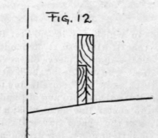
The engine foundation is constructed, as in Fig. 12, of 1 1/2 in. pine plank cut out to fit alongside the keelsons already fitted, and is fastened to them. This gives the necessary width for strength and for fastening with the lag screws. The cross braces between the bearers before mentioned should extend as high as possible and cut out to fit around the engine base. In fitting the bed a line should be run through the stern tube aud extended forward over the engine bed, and by reference to the engine the necessary position of the bed may be determined. The position of the extreme after end of the shaft should be also noted for use in fitting the propeller.
Lining up the engine should be a rather particular piece of work, as the shaft must enter the engine coup ing perfectly straight as otherwise it will bend at every revolution and add friction. The engine, after being lined up, is fastened down with lag screws. The propeller will probably come fitted to the shaft, so that all that shonld be necessary is to put propeller in place on shaft and fasten with either nut or pin, as is provided. The propeller, when in its proper place, should should be 10 in. from the point of stern to center of propeller, and the inboard end of the shaft is cut off to bring the propeller in the proper place.
The propeller strut is shaped as in Fig. 13, from a piece of flat brass lx1/4 in. It is bent to the shape shown, of sufficient depth to suit the shaft and with a spread of about 6 in. For the bearing a piece of extra thick brass tube which is a running fit for the shaft, can be used. It is fitted into the eye and soldered in place. The strut is then adjusted until the bearing is free on the shaft and the arms have a good bearing on the hull, and it is then fastened in place with two copper rivets in each arm. If the rivets cannot be made to come through a frame, a piece of oak should be put inside to take them.
The gland on the after end of the skeg is fitted in place with plenty of thick paint underneath to make it water tight.
An additional bearing should be arranged about half way between the engine and the stuffing box; it can be made of a piece of extra heavy brass tube, the same as the strut bearing and secured in a wooden block. When all is set up and made tight, the engine should turn over freely and easily, otherwise there will be undue friction and the full powerof the engine will not be realized.
The engine selected for use should be of 1 1/2 to 2 h. p., of high speed type, and should not, for best results, weigh over 80 pounds complete with pump.
The installation is made in the usual manner according to the directions which accompany each engine, or can be obtained from the engine makers on request. The gasoline tank should hold about five gallons and be located under the forward deck, supported by straps from the deck above, as in Fig. 5.
The filling pipes for the tank should extend through the deck with a screw cap. The connection from the tank to the engine is 1/4 in. pipe size, lead pipe, with a stop cock near the vaporizer.
A fixture of much value is a sediment trap quite near the tank, made by fitting a brass T to the tank and to the lower end of the T fitting a coupling and plug. Any sediment from the tank will collect in the neck having the plug, which can be removed at times when the tank is nearly empty.
Continue to:
My Books

