A Twenty Five Foot Auxiliary Yawl. II. Making and Setting Up the Stem, Stem and Bottom
Description
This section is from the book "Amateur Work Magazine Vol6". Also available from Amazon: Amateur Work.
A Twenty Five Foot Auxiliary Yawl. II. Making and Setting Up the Stem, Stem and Bottom
Carl H. Clark
The outline of the sternboard having been shown in Fig. 6, the complete stern is shown in Fig. 8. It is of 1 1/4 in. oak or other hard wood, fastened together with cleats 1 1/4 in. thick. It should be formed of a wide piece in the middle, narrower pieces added on the sides to make the necessary width. No joint should come in the middle, as it would make fastening difficult. The cleats are fastened on with galvanized boat nails, and the lower cleat should be at least 15 in. from the lower end, to allow fastening of the stern knee. The round of the upper end need not be cut at present, neither need it be bevelled until set up in place.
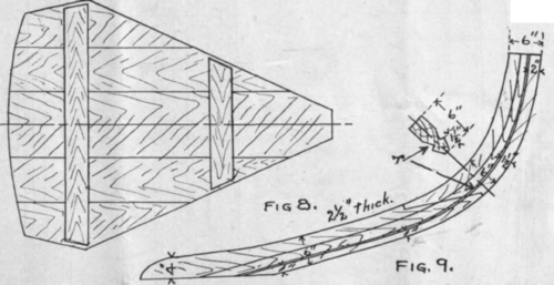
Fig. 9 shows the completed stem, the outline of which is given in Fig. 6. It is 2 1/2 in. thick. While it may be possible to obtain a curved piece out of which it may be cut, it is not likely; therefore it will probably be made in two parts scarphed as shown in the figure. The length of the straight part of the scarph should not be less than 10 in., and its exact position will depend upon the stock obtainable. The two portions are cut out separately and fitted together to match the paper pattern already laid out. They are fastened together with pieces of 8/8 in. galvanized rod riveted over washers inside and outside.
In Fig. 9 r represents the rabbet or triangular groove to take the ends of the plank and bring them in flush with the sides of the stem. The dimensions for laying out this rabbet are given from the face of the stem; these are laid off on both sides and a curve drawn through them. Starting with this line the groove is cut as shown in the small cross section, being about 8/4 in. deep and about 1 1/2 wide. It need only be roughed out now, leaving the finishing to be done after it is in place. The upper end should be left about 6 in. larger than shown, to fasten shores to hold it in place. The flat part outside of the rabbet may also be bevelled off, as shown, to about 7/8 in. on the face.
The outline of the bottom is shown in Fig. 10, and the complete bottom in Fig. 11. It is 1 8/4 in. thick and is best made in three pieces, joined as shown. The pieces are planed on the edges and fitted together. If necessary, two or three temporary cleats may be fastened on to hold them; a center line is struck and the mould points, 3 feet apart, are laid off along it and lines drawn across. The widths from Fig. 10 are now laid off on each line as shown; a fair line may be drawn through these points by using a batten about $ in. square, held in place by rails driven each side of it. The center-board slot should also be laid out.
The boards may now be separated and trimmed down to the line, leaving a square edge. The slot may be cut by boring a few holes near one end sufficient to be sawed out, and then trimmed up with a chisel. The boards are then fastened together permanently by the cleats, as in Fig. 11. These cleats are of oak 2 in. square and about 6 in. longer than the width of the bottom.
The positions of the cleats are as shown, and they all extend across the bottom except the two between moulds 3 and 4, which are cut 2 1/4 in. clear of the centerboard slot. The cleats are square with the center line, and are fastened on with heavy galvanized nails or screws. They should be put on in about the position shown in order to clear the other frames; those marked a a are exactly even with the ends of the centerboard slot.


The bottom may now be turned on edge and a rabbet cut out on the edge, as shown in Fig. 12, using a mallet and heavy chisel. Near the ends it should be cut rather steeper than shown on account of the sharper angle of the frames. This may be accomplished by reducing the 1 1/4 in. dimension to 1 1/8 and finally to 1 in., the others remaining the same. While this rabbet must be carefully cut, it need not be. entirely finished now, as there will be small variations of the angle which cannot be determined until the boat is set up.

FIG. 12.Detail of rabbet.
The stern house, shown in Fig. 14, should be cut to the dimensions given, out of a piece of 3 1/2 in. stock with the grain running from point to point. The exact angle of this knee is quite important, as it fixes the angle of the sternboard, and consequently the shape of the after end of the boat.
The stern and sternboard are now set up in their proper positions on the bottom and clamped temporarily in place; the center line of each must agree with that of the bottom and they must be in the correct fore and aft line or, in other words, point directly ahead and astern, and not to one side. To aid in setting these, the bottom may be laid on a level floor, and a cord stretched from the center of the sternboard to the center of the stem.
A short plumb line may then be held alongside of this cord, and the coincidence or deviations of the point of the bob with the center line of the bottom will show whether they are correctly set. When properiy adjusted they may be fastened into place with 3/8 in. galvanized iron rivets. Rivets for this and other purposes may be bought with the head already formed, or may be formed of a piece of 3/8 in. rod sawed the proper length and headed at either end; the latter is the cheaper way and just as satisfactory.
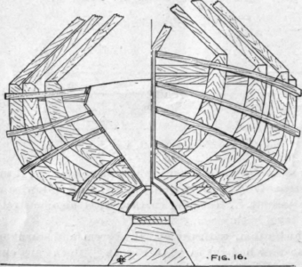
A foundation must now be built upon which to se up the boat in order to bring it to a convenient height for working. This foundation is built as shown in Fig. 15, of a 2 in. spruce plank about 12 in. wide and 20 ft. long, supported about 15 in. above the floor. The supports or braces are pieces of 2 in. plank shaped as in Fig. 16, or other shape which is sufficiently rigid. These supports should be so spaced that one comes under each end and under each mould, as in Fig. 15.
For building the boat a place should be chosen, if possible, where there is a wood floor and strong rafters overhead, as both of these are necessary for ease of bracing and holding the several parts. The founda-

FIG 14. Stern knee.
Fig. 13 Outline of CB.Logs.
tion should now be set up in the place chosen; it must be strongly built and well braced, both sidewise and fore and aft. The upper surface must also be straight and level both ways.
The bottom, with the attached stem and sternboard must now be bent in as in Fig. 15. Blocks are cut to the widths there given, which are fastened to the foundation in the proper places. The bottom is laid on and forced down into the shape thus prepared by shores from the beams above; the judicious use of wedges will help in this operation. The bottom is bent down until it touches the foundation at the middle brace. This operation will require some care, as the bottom is a fairly stiff piece of timber and will require some force to bend it. Owing, also, to the stock which has been cut out at the centerboard slot it will have a tendency to bend more easily at this point, which must be guarded against A liberal amount of boiling water poured over the bottom, or cloths saturated with hot water, will take out some of the stiffness and allow it to bend more easiiy.
An ample number of shores should be used and the final shoring should be placed on either side of the center line, leaving a clear sight down the middle of the boat. The shores must also be kept clear of the mould points.
The moulds, which have already been made, may then be set up in their right places on the bottom, the lower edge of each being slightly bevelled to fit the slope of the bottom at each mould. It is to be noted that the moulds forward of No. 4 are placed forward of the mould point, or with the mould point even with the after face of the mould, and those aft of No. 4 are placed aft of the mould point.
The moulds must be set plumb and also square with the center line fore and aft and must also have their middle points in the center line. The line already used may be again stretched and the moulds adjusted so that the center point already marked on [the cross piece will fall under it. As each mould is adjusted it is fastened by braces, as shown in Fig. 16, run diagonally to the beams overhead. The moulds are fastened to the bottom by cleats nailed to both mould and bottom, and by nails driven in diagonally.
The correctness of the slant of the stem and stern-board may be tested now; the distance from mould point No. 1 to the rabbet at the top of the stem is 3 ft. 8 in. as given in Fig. 2, and from mould point No. 7 to the corresponding point on the sternboard is 4 ft. 1 in.
The angle of the sternboard with a level line should be such that by measuring up along the sternboard 3 ft. from the bottom corner and dropping a plumb the horizontal distance from the corner to this plumb line will be 2 ft. 4 1/2 in.
The stem and sternboard are also well braced so as not to be thrown out of line during the process of building.
A ribband about 2 in. wide and 1 in. thick is now bent around the moulds near the top and fastened in place. As it is bent around, a portion of the edge of each mould is bevelled to allow it to bear evenly on the entire thickness of the mould.
The entire edge of each mould may now be bevelled so that the ribbands, run as in Figs. 15 and 16, will bear evenly at all points. The fairness of the different moulds may now be tested, as the ribbands should bear evenly on every mould and make a fair sweep from stem to stern. Any unfair spots may be corrected, either by trimming off or shimming out as may be necessary.
The rabbet in the bottom and around the stem may be finished out to the correct angle and made ready to receive the plank. The angle of both of these must be such that a plank lying on the moulds will bed fairly into the rabbet at all points. The edge of the sternboard also must be bevelled to the right angle. When this work is completed three or four additional ribbands are bent around when the boat should look as shown in Figs. 15 and 16. Screws should be used, as the ribbands must be removed from time to time.
At the points a a, Fig. 15, where the stern and sternboard join the bottom, stop-waters are to be fitted to prevent the water running in along the joint. A 5-16 hole is bored right through, and a tightly fitting plug driven in and cut off even with the outside surface.
Continue to:
My Books

