Construction And Management Of Gasoline Engines. Spark Coils-Wiring: Diagrams. Continued
Description
This section is from the book "Amateur Work Magazine Vol6". Also available from Amazon: Amateur Work.
Construction And Management Of Gasoline Engines. Spark Coils-Wiring: Diagrams. Continued
Magneto
This is a small dynamo electric machine used to give electric machines wound to give an alternating current; it is run from the flywheel by means of a belt or friction wheel. magneto should be used for steady running, and should be wired so that it may be switched into the circuit after the engine has been started on the batteries. They are comparatively inexpensive, and their use will effect a considerable saving in battery expense in a boat used very frequently.
Wiring
Fig. 42 shows the simple wiring for a single cylinder, make and break spark. The batteries B are connected in series, as before stated; one terminal from the batteries is wired to one terminal of the spark coll C; the other terminal of the coil is connected to the insulated electrodes of the igniting gear. The other battery terminal is fastened to or "grounded" on the metal of the engine. The circuit is thus complete, and may be made and broken by the sparking gear as before described. A switch, S, is inserted to open the circuit and prevent waste of batteries.
When duplicate sets of batteries are used the connections are as shown in Fig. 43, a three point switch s allowing the use of either set.
When a magneto is used in addition to the batteries, one terminal of the magneto is connected to the ground-wire G, and the other terminal to a three point switch, 8. allowing the use of either magneto or batteries.
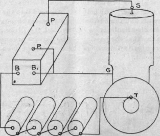
Fig. 45.

Fig. 46.
The typical connection for a jump spark coil to a single cylinder engine is shown in Fig. 44. The coil is represented at C with the binding posts P P, B B, as before; T is the insulated electrode of the timer, and S is the spark plug. G is the " ground " or connection to the metal of the engine. The batteries are connected in series, as shown; from one battery terminal a wire is run to the timer, and the other terminal is connected to one of the primary posts, B. From the other post B a wire is led to the ground G. It is evident that the primary circuit is complete except as made or broken by the timer.
One of the posts P is connected to the spark plug, and the other to the ground, thus making a circuit for the secondary except at the spark gap where it jumps. It will be plain that whenever the connection is made or broken by the timer T a spark, or series of sparks, will take place at the plug S igniting the charge.
It will be noted that there are two ground wires, one leading from each of the posts P and B; these two wires may be replaced by a single wire when the connections are as in Fig. 45, which might be taken as the standard wiring for a four terminal coil.
Since the posts P' and .B'are connected, it is becoming the practice to connect them inside of the coil box and thus dispense with the post P making a three terminal coil, as shown in Fig. 46, which also shows the connections, which are practically the same'as in Fig. 45. In Fig. 47 is shown the additional wiring for two sets of batteries and a dynamo.

Fig. 47. In certain cases, also, a single coil may be used for a double cylinder engine. These are principally in cases of the double opposed type, or in the four cycle type with the pistons moving together. The connections then are as in Fig. 48, using a double pointed cam with a single terminal, giving two contacts for
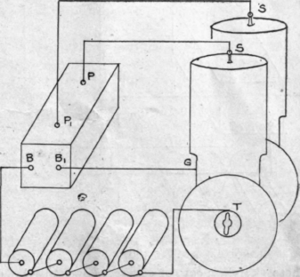
Fig. 48.
each revolution. The usual practice is, however, to use one coil for each cylinder, as in Fig. 49, the general connections being similar to Fig.46. Three terminal coils are shown, but if four-terminal coils are used one of the secondaries is connected over to one of the primaries, as shown by the dotted lines, in a manner similar to that of Fig. 45; there are two insulated posts on the timer, one for each cylinder.
It is customary for multi-cylinder engines to combine all the coils into one box for compactness and simplicity. A common form of duplex coil with con-
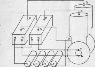
Fig. 49.
nections is shown in Fig. 50, which should be sufficiently plain without further explanation. Another, and perhaps more usual form of duplex coil, is illustrated in Fig. 51, some of the connections being made inside of the box; this sketch again is self explanatory.
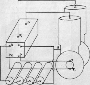
Fig. 50.
These sketches can, of course, show only the connections of the most common forms of coils. Coils are usually accompanied by wiring diagrams showing the connections for different conditions but with the above in mind no difficulty should be experienced. In any of the above diagrams the extra connections for the additional set of batteries or the dynamos may be easily added by following the principle of Fig. 47.
A device for distributing the secondary current is called a "distributor. " It requires the use of only one coil as the secondary current is taken from the coil and sent to each cylinder in turn. In appearance and principle it is like the ordinary timer, in fact both timer and secondary distributor are contained in the same case. The principle is illustrated by Fig. 52 where T is the primary circuit breaker consisting of a cam having as many projections as there are cylinders; these projections rub past the insulated contact piece C and thus make and break the primary

Fig. 51.
circuit. A revolving cam B makes contact with the insulated plates P P P P corresponding to the number of cylinders. One terminal is wired to the arm D, which is insulated from the shaft, the other terminal is grounded on the engine; wires are run from the posts P, to the spark plugs. It is thus plain that whenever the timer T makes and breaks the contact with 0 the arm D will be in the proper position to deliver the secondary current to the proper plug.
The question as to the use of one or the other systems must be a question of the individual conditions; the make and break system is very simple from the electrical standpoint, as the wiring is simple and only low tension current is dealt with. The igniting gear, on the other hand, is apt to be rather complicated, with many small parts which wear and become noisy. This system is well suited to working boats, which are likely to receive little care, and to others where the whole outfit is liable to be exposed to the weather. For extreme high speed the igniting gear is apt to be somewhat erratic, as the springs do not act quickly enough to operate between strokes and it is certainly very noisy at high speed even when in good condition. The cleaning of the sparking points is also likely to be a considerable nuisance, s they are seldom so arranged as to be easily gotten. at.
The jump spark system makes possible a very simple engine, as the only parts required for the ignition are the timer and plug. The engine is free from all ignition gear requiring oiling and care, trouble in the system is usually easily located and remedied; trouble at the sparking points is easily overcome by replacing the plug with another and cleaning up the first at leisure; the timer, also, is easily gotten at and simple.
On the other hand, the wiring is rather more com. plicated and must be most carefully done; the current in the secondary wires is, as before stated, of a very high voltage, and special insulation must be used to prevent leakage. The secondary wiring and coil must be protected from rain or spray, as moisture is sure to cause a short circuit. It is also quite uncomfortable if the current becomes short circuited through any part of the person. With care, however, these points may easily be guarded against and the jump spark system becomes very simple and satisfactory. The outfit of coils and timer is, of course, more expensive than the outfit for the make and break system, but these parts are durable and permanent, and the cost of the complicated igniting gear is saved so that when the complete outfit of engine and accessories is purchased the slight additional cost is not felt. For cabin boats where the machinery is protected from moisture the jump spark is particularly well suited, and there is no reason why it may not be used if desired in almost any circumstances. The secondary coil must, of course, be protected from spray and rain, but this can easily be done by stowing the coil in a convenient loeker or box, and in the case of a shower a piece of canvas may be thrown over engine and wiring.
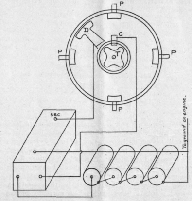
Fig. 52.
Distributers are as yet little used and are fitted for engines of four or more cylinders where the wiring would be more complicated; for small engines their use would not be advised at present.
Continue to:
My Books

