Electrical Equipment Of A Wayside Inn
Description
This section is from the book "Amateur Work Magazine Vol6". Also available from Amazon: Amateur Work.
Electrical Equipment Of A Wayside Inn
W. A. Wakeman
While on a short trip into the country some time ago, I stopped at a wayside inn, and seeing evidence of an electric equipment, I found the engineer and expressed a desire to see his plant. He proceeded to show it and explain its details in a way that made it appear as a pleasure to him, and certainly was a source of satisfaction to myself. Although the plant is not large it is one of the most complete that I have ever seen, and on account of the precautions taken to prevent interruption of the service, it is well worth a complete description in order that others may profit by the foresight herewith displayed.
Fig. 1 is a plan of the plant and is explained as follows:
A horizontal tubular boiler of about 50 horse power is shown at 2, furnishing steam for an old-fashioned automatic cut-off steam engine, 3 having a cylinder about 10 x 30 inches. The fly-wheel of this engine is belted to the main pulley 4, which is on a shaft overhead in the room, and it was located high enough to be well out of the way.
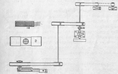
Fig.1.
On the other end of this shaft there is a larger pulley 5 on which is a belt that drives a smaller pulley, 6, thus increasing the speed of the second shaft, which is only about 7 feet above the floor, and is supported on floor stands in the usual way. This shaft carries another pulley 7, which is belted to a dynamo 8, which supplies current at 110 volts to lamps in all parts of the main building, also in several smaller structures and for a beautiful lawn.
The above description covers the plant as run under normal conditions. As the engine runs at a slow speed with three belts between it and the dynamo, it cannot be considered up-to-date and it is not illustrated for this purpose, but it supplies light that is satisfactory for this particular place, and the whole plant was installed at a very low cost.
A vertical high speed engine is shown at 9 and on the outer end of its crank shaft there is one-half of a coupling, 10, and the other half is on the countershaft. There are no bolts in this coupling, therefore the shaft is free to revolve while the engine remains at rest under normal conditions, but if the larger engine should be disabled from any cause, the belt on 6 would be thrown off, bolts put in 10, and the engine, 9, started without delay, thus continuing the service.
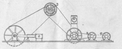
Fig. 2.
This inn was a well and favorably known resort long before trolley lines came into existence, but now a 550-volt system is in operation, a few rods from the house, and from this, a reserve or " break down " ser. vice is secured as follows: In case both engines, 3 and 9 are disabled, or if the boiler 2 should be thrown out of commission so that steam could not be supplied to either engine, the belt on 8 would be thrown off. A 650-volt motor is shown at 11, taking current from the street service, as above mentioned. The belt in dotted lines would be put on, thus making it possible to drive the dynamo 8 by the motor 11.
Current is not taken direct from the street service and used for lighting purposes on account of the difference in voltage, as the former is 550 while the latter is 110. Of course it could be done by wiring five 110 volt lamps in series; but that is not best practice, because if one of these lamps should burn out it would disable four more. Another reason for this arrangement is that it is always desirable to keep the voltage as low as possible, and as the distance over which current is carried in this case is short, there is no need of a high tension.
Although we usually think of a rotary transformer as a compact machine without belts, as both motor and dynamo are on one shaft, still a consideration of this outfit shows that the dynamo 8 taken in connection with the motor 11 with a belt connecting them, constitutes a rotary transformer for a direct current, reducing it from 550 to 110 volts.
A storage battery is shown at 12 that is charged during the day for use in an emergency at nighl, therefore if both engines 3 and 9 were disabled and the trolley service cut off from 11, the lights could still be supplied for one evening from this storage battery.
Fig. 2 still further illustrates this plant, as it is an elevation of it, in which 2 is the slow speed eugine belted to the main shaft 3 from which a belt is carried down to shaft near the floor that can be coupled to the vertical high speed engine 4 whenever it is wanted to drive the dynamo 6. The motor is shown at 6 with the belt to be used in emergencies in dotted lines.
As the trolley line above mentioned is several miles long, there is more or less danger of lightning striking it and following the wires into this plant, especially as a portion of the trolley line extends over a mountain. To prevent accidents from this source a lightning arrester was installed at the inn. A few days previous to the time that I saw it lightning did come in over the line, and it did not leave enough of that arrester to make decent scrap. Instead of providing a more efficient arrester they simply connected the two, ends of the line together and concluded it was just as well to get along without anything of the kind.
This appears to be a wrong idea, as it is about the same as running a boiler without a safety valve. It will do no harm so long as only a low pressure is carried, but nobody knows how soon a high pressure will be generated, proving disastrous. We are told that lightning does not strike twice in the same place, but this is not strictly true, and if it was it would not prove a safeguard to this place, because the line might be struck several miles distant and current at a very high tension carried into the inn and cause a disastrous fire.
An elevated tank is provided at this place from which a supply of water under pressure is available-A low service direct acting steam pump is provided for filling this tank. In addition to this, the regular boiler feed pump is piped so that by opening and closing certain valves, it can discharge into the tank in case the low service pump fails.
If both of these pumps are disabled or there is no steam by which to operate them, a hot air pumping engine is installed so that it can be used, for this service, and this, of course, is entirely independent of all other sources of power. A wind mill is used for filling this tank when a brisk breeze is blowing.
The buildings comprising this establishment are heated by steam and the water of condensation flows into a receiver from which it is taken by a pump in the usual way, and pumped into the boiler. As there is always at least a slight loss of water in such cases, arrangements are made whereby fresh water can be turned directly into this receiver, thus making this pump a complete boiler feeder independently of the regular cold water pump.
When the receiver pump is out of order, hot water from the drip pipe is allowed to run to waste temporarily, while fresh water is pumped in by the regular boiler feeder, thus providing two ways of feeding the boiler.
The foregoing description is not intended to convey the idea that the machinery in this plant is more liable to be disabled than that installed in other places, but it is expected to illustrate the good judgment shown in designing the plant to prevent accidents that will interfere with the continuous service expected, and in this respect it is far superior to some more pretentious plants that are found in cities, where everything is supposed to be almost or quite perfect. -" National Engineering."
Continue to:
My Books

