Elements Of Dynamo Design. III. Equasion of the Dynamo. The Armature
Description
This section is from the book "Amateur Work Magazine Vol6". Also available from Amazon: Amateur Work.
Elements Of Dynamo Design. III. Equasion of the Dynamo. The Armature
IRA M. CUSHING
Before proceeding into the fundamental equation of the dynamo, the principle under which the current is generated must be studied. In 1831 Faraday discovered that if a closed conductor be moved across a field of magnetism an electric current would be generated in the conductor. By closed conductor is meant a loop or coil of wire with the ends fastened together to make a complete circuit. Faraday further discovered that an electric current so generated flowed in a direction at right angles to the direction of motion and at right angles to the lines of force.
Later Dr. Fleming worked out his graphic illustration of the rule, which is this:-Point the thumb, first, and second fingers of the right hand so that they will be approximately at right angles to each other. (See Fig. 9.) With the thumb representing the direction of motion of the conductor, the first finger representing the direction of the lines of force, the second finger will represent the conductor and will point in the direction in which the current will flow in it. In passing, it might be useful to note that the left hand will represent the motor. In this case there is given the direction of the current in the armature conductors and the direction of the lines of force, and then the thumb will give the direction of rotation of the armature. These two rules are very useful to remember and sometimes save much time.
Faraday proved, after many experiments, that the E. M. F. induced in this coil of conductors was directly proportional to the number of lines of force cut per second. From this it is readily seen, therefore, that the E. M. F. is proportional to the speed with which the conductor moves through the field of force, to the number of lines per square inch or magnetic density, and also to the length of the conductor in the magnetic field. Since the length of the conductor in the field and the magnetic density are both components of the total number of line of force, the latter term is used, which serves to simplify formulae and calculations.
The expression, "moving across a field of magnetism," has been used to explain the generation of current in a conductor. This implies cutting of lines of force. These expressions serve best in working out a formula for the result, but the following is probably a better explanation of the action. It is evident that if a piece of wire with its ends apart is passed through a field of force no current is generated, as there is no chance for it to flow although there may be what is called a "difference of potential" between the two ends; that is, there is a tendency for current to flow. If the ends are brought together to make a closed coil, and this coil be moved in a uniform field of force (where the density is everywhere the same) in a direction at right angles to the lines of force, its axis always paranel with the lines, no current will be generated in it. If, however, the coil be moved to a denser or less dense portion of the field, or into another adjoining field where the lines go in an opposite direction, an E. M. F. will be generated. Or if the coil be turned on an axis at right angles to the
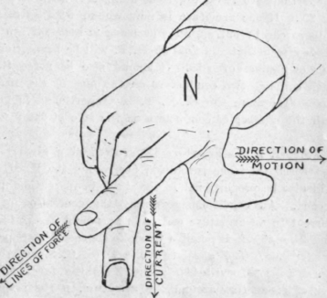
Fig. 9.
lines of force, then an E. M. F. will be induced. In the first instance the conductors of the coil were all cutting lines of force, but during all the motion the number of lines threading through the coil remained the same; for every line coming in at the front a line passed out at the back. In the other instances the number of lines threading through the coil changed as it moved, and experiment shows that the E. M. F. induced in the coil is directly proportional to the rate of change. Fig. 10 represents a simple dynamo. W is a coil of wire centered on and rotated by shaft A-A, and placed in the field of force produced by the N and S poles. Each end of the coil is connected to a segment in the two-piece commutator C, and by means of the brushes B.B, and the external circuit D, the path for the E. M. F. generated in the coil is completed. When the coil is placed as shown with its plane at right angles to the lines of force, the maximum number of lines are threading through it.
If the coil be turned on its axis, or shaft A,-A, through an angle of 90 degrees, or until its plane is parallel with the field of force, the number of lines going through will become zero. Another turn of 90 degrees would bring the coil to the position of maximum lines again. During this half turn E. M. F. would be generated in the coil and this E. M. P. would be proportional to the rate of change of lines through the coil. This rate of change is equal to' the total number of lines in the field, and the coil in turning cut the total number of lines. Therefore, when an armature is so placed in a field that the total lines can, during some portion of a revolution, thread through the coils the number of lines cut by a conductor are equal to the rate of change of lines threading through the coils. The next half turn of the coil completes one revolution and also repeats the process of generating E. M. F.
It is seen, therefore, that the E. M. F. generated is proportional to twice the total number of lines of force or 2N. If the armature is now wound with as many coils as can be put on, all coils being in series, it can be readily seen that the final E. M. F. will be proportional to the number of coils. It should also be noted that each coil has two conductors on the face of the armature. Therefore the E. M. F. is proportional to one-half the number of conductors on the face of the armature.
Further, if the armature is revolved at a greater or less speed than one revolution per second the E. M. F. will also be proportional to the speed in revolutions per second. All conditions governing the generation of a current in an armature coil have now been ascertained, and from this it is possible to make a general statement or formula. The absolute volts E (C. G. S. unit) is equal to 1/2Z X n X 2N, where Z is the total number of conductors around the armature, n the revolutions per second and N the total lines of force. The 1/2 and the 2 cancel each other and the formula reads:
E (C. G. S. units) = nZN ( 11 ) The volt of the C. G. S. system is entirely too small for practical use as it it takes 100,000,000, or 108 as it is designated, of them to make one practical volt as now used.
Formula 11 will therefore become
E (practical volts) = E(C.G.S.) / 108 = nZN / 108
This, then, is the fundamental equation of the dynamo and is used, with a few modifications, for designing all machines. Forrrmla 12 is correct for two pole dynamos. For more than two poles it becomes
E = p /c x n Z N / 108 (13) in which p is the number of poles and c the number circuits in parallel in the armature from brush to brush. Now that the equqation of the dynamo armature has been worked out, it would be well to study a little closer into what takes place in the coil as it turns in the field of force. Referring to Fig. 10, if the coil is turned 180 degrees to the right it will be found, accord-

Fig. 10.
ing to Fleming's rule of thumb and fingers, that the E. M. F. will flow from n to m while that conductor is moving from top to bottom of the field. Turning the coil the rest of the way around to its original position, and applying Fleming's rule, shows that the E. M. F. flows from m to n, or just the reverse of the first half revolution. It will be readily seen from this that for the first half E M. F. will flow out of the brash R, which is attached to the m end of the coil, and for the second half revolution will flow in at R coming out at brush T. Circuit F will then receive a pulsating or alternating E. M. F.
As alternating E. M. F. is not what is wanted, some scheme must be devised to change the direction of the E. M. F. at the same moment that it is changed in the coil. By making this double change it will be possible to obtain a continuous flow of E. M. F. The device used is a commutator, as shown at c, Fig. 10. This consists of two segments of metal, preferably copper, thoroughly insulated from each other, the entire surface being cylindrical. One end of the coil is attached to one segment and the other end of the coil to the other segment. Two brushes made of a spring metal bear on the commutator and are set so that they touch the commutator at diametrically opposite points. Now, if the brashes are set so that they slip from one segment to the other at just the time the E. M. F. changes direction in the coil, it will be found that the E. M. F. will always flow out of the top brush A in Fig. 11. It will be seen, from this figure, that the rate of change of lines in the coil will change from an increasing rate to a decreasing rate as the coil passes the vertical position. Or applying Fleming's rule, the direction of motion of the conductor changes from going up on the left to going down on the right and the change will take place as the coil passes the vertical position. The brushes A and B are, therefore, set to change from one segment to the other as the coil passes the perpendicular. As the conductor m passes down the south pole the E. M. F. generated will come towards the observer, and as brush A is in contact with segment in. the E. M. F. will flow out from that brush through the circuit back to brush B. As conductor m continues around and moves up the north pole, Fleming's rule, will show that the E. M. F. generated will flow away
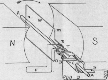
Fig. 11. from the observer. But in the mean time A has slipped on to the segment and Bis in contact with m. Now by the same rule, n is delivering E. Ml F. to brush A. It will be easily seen, therefore, that brush A will be in contact with the segment connected to the conductor moving down along the south pole and which is generating E. M. F. that flows towards the observer. Brush A is, therefore, always delivering E. M. F. to the circuit and is consequently called the positive, +, brush and B will be the negative, -, brush.
Continue to:
My Books

