Induction Coil Winding Machine
Description
This section is from the book "Amateur Work Magazine Vol6". Also available from Amazon: Amateur Work.
Induction Coil Winding Machine
Frederick A. Draper
A method of coil winding described in the October issue of this magazine required the use of a screw-cutting lathe with gears set as for cutting 60 threads to the inch. As many readers who might like to make coils after this method may not possess a screw-cutting lathe, and as a simple yet adequate winding machine can be made at small expense, such a machine is here described. It also possesses one decided advantage over a lathe, and that is the ability to stop winding, instantly at any time. While a lathe is very apt to run ever or the wire to twist or break if too sudden a stop is male.
The way to use such a machine is to mount the bobbin on the winding shaft, pass the bare wire between the two screws and fasten the end to the bobbin, allowing sufficient:free, wire for subsequent connections. The wire is then held by the fingers so that, as the winding proceeds, the wire will be in the turns of the screw and be guided across the bobbin. To reverse the direction it is simply necessary to use the other screw, the top side of the lower screw and the under side of the upper screw turning in opposite directions.
The construction of the winder is shown in the accompanying drawings. The frames are of cast iron,
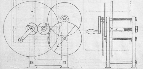
On this machine secondary windings may be wound up to 10 inches in diameter; a size quite as large as any reader is likely to attempt. In Fig. 2 will be noted two screws with 20 threads to the inch. On the left ends of these screws are gears of 6 in. pitch diameter, meshing with an intermediate gear 2 in. diameter, which in turn meshes with a 2 in. gear on the winding shaft.
It will be noted that the ratio of the gear on the winding shaft to those on the screws is 1 to 3; three turns of the former are required, therefore, to get one of the latter. As the screws are cut twenty threads to the inch, this enables wire to be wound on the bobbin turning on the winding shaft with 60 turns per inch; the number specified in the article on coil winding referred to. By varying the ratio of the gear any number of turns of wire can be provided for. The in-termediate gear may be of any convenient diameter that on the right side having no winding shaft bearing or supporting arms. A 1/2 in. hole is drilled for the winding shaft, W. The shaft is fitted with a face plate P of the size required for the coils to be wound, and a turning crank fitted to the left end outside the gear. The right end is threaded to receive a nut for tighten-ing up another faceplate or bobbin end. A shaft 6 in.' long will be ample for all ordinary needs, 3 1/2 in. of this length being to the right of the inner face plate.
The screw shafts are about 6 1/2 in. long; 2 in. at; the left end being | in. in diameter, without threads, then 3 1/2 in. threaded, 20 threads per inch, and 1 in. on the right end turned down to 1/4 in. The gears fitted to the screws should have hubs and set screws, for fastening to the screws. The intermediate gear runs on a stud. In drilling the holes in the frame for 'the' bearings of the shafts, care must be used in spacing them so that the gears wi run without binding or too much play- The easiest way to be sure of this is to have the gears made and at hand before drilling holes for the stud and screws.
At the bottom of the frame are two tie rods with nutsjat the ends, these being necessary to secure a rigid frame. The gears have such light duty that they need not be over 1/8 in. thick, except the intermediate gear which "must be thick enough to drive both screw gears or about 5-16 or | in. thick. The threads on the screw shafts may be cut with a common die, any broken threads being smoothed off with a V needle file, so that the wire will not catch and break.
Continue to:
My Books

