Gasoline Burner For Model Work
Description
This section is from the book "The Boy Mechanic Vol. 1", by Popular Mechanics Co.. Also available from Amazon: 700 Things for Boys to Do.
Gasoline Burner For Model Work
When making a small model traction engine or a locomotive the question arises, "What shall the fuel be?" If you have decided to use gasoline, then a suitable burner is necessary. A piece of brass tubing about 3 in. in diameter and 6 in. long with caps screwed on both ends and fitted with a filling plug and a bicycle valve makes a good gasoline supply tank, says the Model Engineer, London. The bicycle valve is used to give the tank an air pressure which forces the gasoline to the burner.
The burner is made from a piece of brass tube, A, as is shown in the illustration, 1/2 in. in diameter and 2-1/2 in. long, which is plugged up at both ends, one end being drilled and reamed out to 5/16 in. Three rows of holes 1/16 in. in diameter are drilled in the brass tube. One row is drilled to come directly on top, and the other two at about 45 degrees from the vertical. It is then fitted to a sheet steel base, B, by means of the clips, C C, Fig. 1. A piece of 1/8-in. copper pipe, P, is then coiled around the brass tube, A, which forms the vaporizing coil. This coil should have a diameter of only 1 in. One end of the copper tube is bent around so it will point directly into the reamed-out hole in the end of the brass tube, A. A nipple, N, is made by drilling a 1/8-in. hole halfway through a piece of brass and tapping to screw on the end of the 1/8-in. copper pipe. A 1/64-in. hole is then drilled through the remaining part of the nipple. The other end of the copper tube is connected to the supply tank. The distance between the nipple, N, and the ends of the tube, A, should be only 5/16 of an inch. Fig. 2 shows the end view.
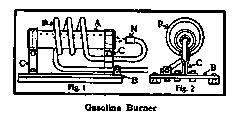
Illustration: Gasoline Burner
Continue to:
More:
- Removing Grease Stains From The Leaves Of A Book
- How To Construct An Annunciator
- To Make A Magazine Binder
- A Fishhook Box
- An Austrian Top
- Rolling Uphill Illusion
My Books

