Faure's Machine For Decorticating Sugar-Cane
Description
This section is from "Scientific American Supplement". Also available from Amazon: Scientific American Reference Book.
Faure's Machine For Decorticating Sugar-Cane
The object of the apparatus shown in the accompanying engraving is to effect a separation of the tough epidermis of the sugar-cane from the internal spongy pith which is to be pressed. Its function consists in isolating and separating the cells from their cortex, and in putting them in direct contact with the rollers or cylinders of the mill. After their passage into the apparatus, which is naturally placed in a line with the endless chain that carries them to the mill, the canes arrive in less compact layers, pass through much narrower spaces, and finally undergo a more efficient pressure, which is shown by an abundant flow of juice. The first trials of the machine were made in 1879 at the Pointe Simon Works, at Martinique, with the small type that was shown at the Paris Exhibition of 1878. These experiments, which were applied to a work of 3,000 kilos of cane per hour, gave entire satisfaction, and decided the owners of three of the colonial works (Pointe Simon, Larcinty, and Marin) to adopt it for the season of 1880.
The apparatus is shown in longitudinal section in Fig. 1, and in plan in Fig. 2.
Fig. 3 gives a transverse section passing through the line 3-4, and Fig. 4 an external view on the side whence the decorticated canes make their exit from the apparatus.
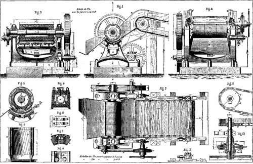
FAURE'S MACHINE FOR DECORTICATING SUGAR CANE.
The other figures relate to details that will be referred to further along.
The Decorticating Cylinder
The principal part of the apparatus is a hollow drum, A, of cast iron, 430 mm. in internal diameter by 1.41 m. in length, which is keyed at its two extremities to the shaft, a. Externally, this drum (which is represented apart in transverse section in Fig. 5) has the form of an octagonal prism with well dressed projections between which are fixed the eight plates, C, that constitute the decorticating cylinder. These plates, which are of tempered cast iron, and one of which is shown in transverse section in Fig. 7, when once in place form a cylindrical surface provided with 48 helicoidal, dentate channels. The length of these plates is 470 mm. There are three of them in the direction of the generatrices of the cylinder, and this makes a total of 24. All are strengthened by ribs (as shown in Fig. 8), and each is fixed by 4 bolts, c, 20mm. in diameter. The pitch of the helices of each tooth is very elongated, and reaches about 7.52 m. The depth of the toothing is 18 mm.
Frame And Endless Chain
The cylinder thus constructed rotates with a velocity of 50 revolutions per minute over a cylindrical vessel, B', cast in a piece with the frame, B. This vessel is lined with two series of tempered cast iron plates, D and D', called exit and entrance plates, which rest thereon, through the intermedium of well dressed pedicels, and which are held in place by six 20-millimeter bolts. Their length is 708 mm. The entrance plates, D, are provided with 6 spiral channels, whose pitch is equal to that of the channels of the decorticating cylinder, C, and in the same direction. The depth of the toothing is 10 mm.
The exit plates, D', are provided with 7 spiral channels of the same pitch and direction as those of the preceding, but the depth of which increases from 2 to 10 mm. The axis of the decorticating cylinder does not coincide with that of the vessel, B', so that the free interval for the passage of the cane continues to diminish from the entrance to the exit.
The passage of the cane to the decorticator gives rise to a small quantity of juice, which flows through two orifices, b', into a sort of cast iron trough, G, suspended beneath the vessel. The cane, which is brought to the apparatus by an endless belt, empties in a conduit formed of an inclined bottom, E, of plate iron, and two cast iron sides provided with ribs. These sides rest upon the two ends of the vessel, B', and are cross-braced by two flat bars, e, to which is bolted the bottom, E. This conduit is prolonged beyond the decorticating cylinder by an inclined chute, F, the bottom of which is made of plate iron 7 mm. thick and the sides of the same material 9 mm. thick. The hollow frame, B, whose general form is like that of a saddle, carries the bearings, b, in which revolves the shaft, a. One of these bearings is represented in detail in Figs. 9 and 10. It will be seen that the cap is held by bolts with sunken heads, and that the bearing on the bushes is through horizontal surfaces only. In a piece with this frame are cast two similar brackets, B², which support the axle, h, of the endless chain. To this axle, whose diameter is 100 mm., are keyed, toward the extremities, the pinions, H, to which correspond the endless pitch chains, i.
These latter are formed, as may be seen in Figs. 11 and 12, of two series of links. The shorter of these latter are only 100 mm. in length, while the longer are 210 mm., and are hollowed out so as to receive the butts of the boards, I. The chain thus formed passes over two pitch pinions, J, like the pinions, H, that are mounted at the extremities of an axle, j, that revolves in bearings, I', whose position with regard to the apparatus is capable of being varied so as to slacken or tauten the chain, I. This arrangement is shown in elevation in Fig. 13.
Transmission
The driving shaft, k, revolves in a pillow block, K, cast in a piece with the frame, B. It is usually actuated by a special motor, and carries a fly-wheel (not shown in the figure for want of space). It receives in addition a cog-wheel, L, which transmits its motion to the decorticating cylinder through, the intermedium of a large wooden-toothed gear wheel, L'. The shaft, a, whose diameter is 228 mm., actuates in its turn, through the pinions, M' and M, the pitch pinion, N, upon whose prolonged hub is keyed the pinion, M. This latter is mounted loosely upon the intermediate axle, m. Motion is transmitted to the driving shaft, h, of the endless chain, I, by an ordinary pitch chain, through a gearing which is shown in Fig. 12. The pitch pinion, N', is cast in a piece with a hollow friction cone, N², which is mounted loosely upon the shaft, h, and to which corresponds a second friction cone, O. This latter is connected by a key to a socket, o, upon which it slides, and which is itself keyed to the shaft, h.
The hub of the cone, O, is connected by a ring with a bronze nut, p, mounted at the threaded end of the shaft, h, and carrying a hand-wheel, P. It is only necessary to turn this latter in one direction or the other in order to throw the two cones into or out of gear.
If we allow that the motor has a velocity of 70 revolutions per minute, the decorticating cylinder will run at the rate of 50, and the sugar-cane will move forward at the rate of 12 meters per minute.
This new machine is a very simple and powerful one. The decortication is effected with wonderful rapidity, and the canes, opened throughout their entire length and at all points of their circumference, leave the apparatus in a state that allows of no doubt as to what the result of the pressure will be that they have to undergo. There is no tearing, no trituration, no loss of juice, but merely a simple preparation for a rational pressure effected under most favorable conditions.
The apparatus, which is made in several sizes, has already received numerous applications in Martinique, Trinidad, Cuba, Antigua, St. Domingo, Peru, Australia, the Mauritius Islands, and Brazil. - Publication Industrielle.
Continue to:
My Books

