


Joy's Reversing And Expansion Valve Gear
Description
This section is from "Scientific American Supplement". Also available from Amazon: Scientific American Reference Book.
Joy's Reversing And Expansion Valve Gear
Four years ago, in August, 1880, a paper was read on this subject before the Annual Summer Meeting of the Mechanical Engineers' Society of Great Britain, then held in Barrow-in-Furness, describing this valve motion and its functions, which was then comparatively new. It was, however, illustrated by its application to a large express goods (freight) engine, built by the London and North-Western Railway Company (England) specially to test the advantages and the endurance of the gear. This engine had cylinders of 18 inches in diameter and 24 inch stroke, and six wheels coupled 5 feet 1 inch diameter, and was designed by Mr. Webb, the Company's chief engineer, for their heavy fast goods traffic on the main line. The engine has been running this class of traffic ever since. In January, 1884, it was passed through the repair shops for a general overhauling, when it was found that the valve motion was in such good condition as to be put back on the engine without any repairs.
The main object of this present paper is to deal with the advantages of the valve gear and its application to various classes of engines both on land and at sea, and with the results of such applications, rather than treating it as a novelty, to give an exhaustive description of its construction and functions, which was done in the paper above referred to. A very short description of its action and main features will, however, be necessary to the completeness of the paper, and as a basis from which the improved results to be recorded should necessarily be shown to spring.
The essential feature of this valve gear is that movement for the valve is produced by a combination of two motions at right angles to each other; and by the various proportions in which these are combined, and by the positions in which the moving parts are set with regard to each other, it gives both the reversal of motion and the various degrees of expansion required. Eccentrics are entirely dispensed with and the time-honored link gear abandoned, the motion is taken direct from the connecting rod, and by utilizing independently the backward and forward action of the rod, due to the reciprocation of the piston, and combining this with the vibrating action of the rod, a movement results which is suitable to work the valves of engines, allowing the use of any proportions of lap and lead desired, and giving an almost mathematically correct "cut-off" for both sides of the piston and for all points of expansion intermediately, as well as a much quicker action at the points of "cut-off" and "release" than is given by a link gear.
The machinery for accomplishing this is both less costly and less complicated than the ordinary link motion, and is shown in elevation on cut, which is a view of the complete motion as on the first London and North-Western locomotive. Here E is the main valve lever, pinned at D to a link, B, one end of which is fastened to the connecting rod at A, and the other end maintained in about the vertical by the radius rod, C, which is fixed at the point, C¹. The center or fulcrum, F, of the lever, E, partaking of the vibrating movement of the connecting rod at the point, A, is carried in a curved slide, J, the radius of which is equal to the length of the link, G, and the center of which is fixed to be concentric with the fulcrum, F, of the lever when the piston is at either extreme end of its stroke. From the upper end of the lever, E, the motion is carried direct to the valve by the rod, G. It will be evident thus that by one revolution of the crank the lower end of the lever, E, will have imparted to it two different movements, one along the longer axis of the ellipse, traveled by the point, A, and one through its minor axis up and down, these movements differing as to time, and corresponding with the part of the movement of the valve required for lap and lead, and that part constituting the port opening for admission of steam.
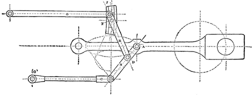
JOY'S REVERSING AND EXPANDING VALVE GEAR.
The former of these is constant and unalterable, the latter is controllable by the angle at which the curved slide, J, may be set with the vertical.
It will further be evident that if the lever, E, were pinned direct to the connecting rod at the point, A, which passes through a practically true ellipse, it would vibrate its fulcrum, F, unequally on either side of the center of the curved slide, J, by the amount of the versed sine of the arc of the lever, E, from F D; it is to correct this error that the lever, E, is pinned at the point, D, to a parallel motion formed by the parts, B and C. The point, D, performing a figure which is equal to an ellipse, with the error to be eliminated added, so neutralizing its effect on the motion of the fulcrum, F.
The "lap" and "lead" are opened by the action of the valve lever acting as a lever, and the port opening is given by the incline of the curved slide in which the center of that lever slides, and the amount of this opening depends upon the angle given to that incline. When these two actions are in unison, the motion of the valve is very rapid, and this occurs when the steam is being admitted. Then follows a period of opposition of these motions, during which time the valve pauses momentarily, this corresponding to the time when the port is fully open. Further periods of unison follow, at which time the sharp "cut-off" is obtained.
The "compression" resulting with this gear is also reduced to a minimum, owing to the peculiar movement given to the valves (i. e., the series of accelerations and retardations referred to), as, while the "lead" is obtained later and quicker, the port is also shut for "compression" later and quicker, doing away with the necessity for a special expansion valve, with its complicated and expensive machinery, and allowing the main valve to be used for expansion, as the "compression" is not of an injurious amount, even with a "cut-off" reduced to 15 per cent., or about 1/6 of the stroke.
Continue to:


My Books

