Planetary Wheel Trains. IV
Description
This section is from "Scientific American Supplement". Also available from Amazon: Scientific American Reference Book.
Planetary Wheel Trains. IV
By Prof. C.W. MacCORD, Sc. D.
Continued From Scientific American Supplement, No. 451, Page 7192
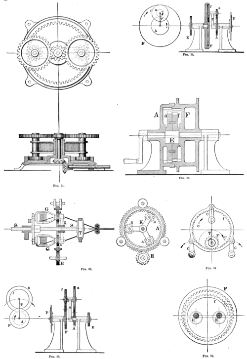
The arrangement of planetary wheels which has been applied in practice to the greatest extent and to the most purposes, is probably that in which the axial motions of the train are derived from a fixed sun wheel. Numerous examples of such trains are met with in the differential gearing of hoisting machines, in portable horse-powers, etc. The action of these mechanisms has already been fully discussed; it may be remarked in addition that unless the speed be very moderate, it is found advantageous to balance the weights and divide the pressures by extending the train arm and placing the planet-wheels in equal pairs diametrically opposite each other, as, for instance, in Bogardus' horse power, Fig. 31.
PLANETARY WHEEL TRAINS.
In trains of this description, the velocity ratio is invariable; which for the above-mentioned objects it should be. But the use of a planetary combination enables us to cause the motions of two independent trains to converge, and unite in producing a single resultant rotation. This may be done in two ways; each of the two independent trains may drive one sun-wheel, thus determining the motion of the train-arm; or, the train-arm may be driven by one of them, and the first sun-wheel by the other; then the motion of the second sun-wheel is the resultant. Under these circumstances the ratio of the resultant velocity to that of either independent train is not invariable, since it may be affected by a change in the velocity of the other one. To illustrate our meaning, we give two examples of arrangements of this nature. The first is Robinson's rope-making machine, Fig. 32. The bobbins upon which the strands composing the rope are wound turn freely in bearings in the frames, G, G, and these frames turn in bearings in the disk, H, and the three-armed frame or spider, K, both of which are secured to the central shaft, S. Each bobbin-frame is provided with a pinion, a, and these three pinions engage with the annular wheel, A. This wheel has no shaft, but is carried and kept in position by three pairs of rollers, as shown, so that its axis of rotation is the same as that of the shaft, S; and it is toothed externally as well as internally.
The strands pass through the hollow axes of the pinions, and thence each to its own opening through the laying-top, T, fixed upon S, which completes the operation of twisting them into a rope. The annular wheel, A, it will be perceived, may be driven by a pinion, E, engaging with its external teeth, at a rate of speed different from that of the central shaft; and by varying the speed of that pinion, the velocity of the wheel, A, may be changed without affecting the velocity of S.
It is true that in making a certain kind of rope, the velocity ratio of A and S must remain constant, in order that the strands may be equally twisted throughout; but if for another kind of rope a different degree of twist is wanted, the velocity of the pinion, E, may be altered by means of change-wheels, and thus the same machine may be used for manufacturing many different sorts.
The second combination of this kind was devised by the writer as a "tell-tale" for showing whether the engines driving a pair of twin screw-propellers were going at the same rate. In Fig. 33, an index, P, is carried by the wheel, F: the wheel, A, is loose upon the shaft of the train-arm, which latter is driven by the wheel, E. The wheels, F and f, are of the same size, but a is twice as large as A; if then A be driven by one engine, and E by the other, at the same rate but in the opposite direction, the index will remain stationary, whatever the absolute velocities. But if either engine go faster than the other, the index will turn to the right or the left accordingly. The same object may also be accomplished as shown in Fig. 34, the index being carried by the train-arm. It makes no difference what the actual value of the ratio A/a may be, but it must be equal to F/f: under which condition it is evident that if A and F be driven contrary ways at equal speeds, small or great, the train-arm will remain at rest; but any inequality will cause the index to turn.
In some cases, particularly when annular wheels are used, the train-arm may become very short, so that it may be impossible to mount the planet-wheel in the manner thus far represented, upon a pin carried by a crank. This difficulty may be surmounted as shown in Fig. 35, which illustrates an arrangement originally forming a part of Nelson's steam steering gear. The Internal pinions, a, f, are but little smaller than the annular wheels, A, F, and are hung upon an eccentric E formed in one solid piece with the driving shaft, D.
The action of a complete epicyclic train involves virtually and always the action of two suns and two planets; but it has already been shown that the two planets may merge into one piece, as in Fig. 10, where the planet-wheel gears externally with one sun-wheel, and internally with the other.
But the train may be reduced still further, and yet retain the essential character of completeness in the same sense, though composed actually of but two toothed wheels. An instance of this is shown in Fig. 36, the annular planet being hung upon and carried by the pins of three cranks, c, c, c, which are all equal and parallel to the virtual train-arm, T. These cranks turning about fixed axes, communicate to f a motion of circular translation, which is the resultant of a revolution, v', about the axis of F in one direction, and a rotation, v, at the same rate in the opposite direction about its own axis, as has been already explained. The cranks then supply the place of a fixed sun-wheel and a planet of equal size, with an intermediate idler for reversing the, direction of the rotation of the planet; and the velocity of F is
Continue to:
My Books

