Reaction Time For Turning The Eye To A New Point Of Regard. Part 2
Description
This section is from the book "Human Vitality And Efficiency Under Prolonged Restricted Diet", by Francis G.BENEDICT, Walter R. Miles, Paul Roth, And H. Monmouth Smith. Also available from Amazon: Human Vitality and Efficiency Under Prolonged Restricted Diet.
Reaction Time For Turning The Eye To A New Point Of Regard. Part 2
Explanation of Figure 30. F, focusmg hood of camera; G, ground class focusing screen; B, by-pass oil cylinders; P, photographic plate in frame which moves downward with the flow of oil; S, shutter to expose P, opened by cord, 1. when P is completely raised and closed by cord, 2, at the completion of the fall of the plate; C, sliding contact operated by the movements of the plate-holder; D, drip-pan for oil; T, foot treadle operating a pawl on a toothed wheel at V by which the whole camera is moved short distances to the left for successive eye reactions; W, weight to keep taut the cord connecting the camera to V; X, strings by which the experimenter may operate the exposure apparatus not shown in this figure.
Explanation Of Figure 31
All three measurements employed the Blix-Sandstrom kymograph. See fig. 28 for wiring diagram.
F.position of foot when recording patellar reflexes; B, light wooden bar, the right end of which rests against patellar tendon; H, pendulum hammers which, when released by the electromagnets,M, fall against B and produce stimulus for reflexes; S, movable base carrying the frame for M and H adjustable to height for different subjects by 1, 2. and 3; A, adjustable connection between quadriceps muscle and recording lever. E, exposure apparatus forword reactions in position clamped to post, P; W, window in which the words appear; V,voice key for reaction of subject.
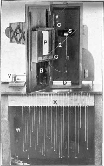
Fig. 30. - Details of the falling plate camera and accessories used in recording eye reactions. The experimenter's end of the apparatus.
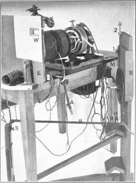
Fig. 31. - The apparatus used in room B for patellar reflex, word reactions, and finger movements.
A sliding contact was arranged at C (figure 30) in the camera. This completed a circuit for the small solenoid S (see figures 34 and 35). This by its action caused the light to be turned on the eye of the subject at the same instant that the stimulus should appear. After the plate had completed half its fall the current was cut off from the solenoid by the breaking of the contact. This contact, C, was composed of two slots in a hard-rubber block, the slots running slightly diagonal to the perpendicular movement of the plate. A small wire brush placed at the upper right-hand corner of the plate-holder moved in these slots. When the plate was at the top this brush was in such a position that it slid down the left-hand slot, which was lined with copper. It thus completed the circuit and actuated the solenoid mentioned. In its downward course the brush was gradually drawn to the left. When the plate had passed half its fall and the brush left its path, it swung back in such a position that when the plate-holder was raised it traveled up the path at the right, which, being composed of hard rubber, did not complete the circuit through the solenoid. In this way the stimulus and exposure of the eye did not have to be separately operated, but were automatically timed in relation to the fall of the plate.
The strings which hang from the end of the table (see X in figure 30) connect with the stimulus device. As the operator sits at this end of the table behind the camera they are in easy position for him to use.2 The easily controlled and silent action of the stimulus apparatus, the accurate means for shifting the position of the camera, the automatic action of the shutter to avoid the fogging of the plate, and the automatic timing of the stimulus in relation to the fall of the plate, all contributed to make possible the taking of reactions with a minimum loss of time. If it is not the first time the subject has served in the experiment, 6 to 8 minutes is ample for the taking of two plates, that is, a total of 25 to 35 reactions. These modifications also help to make possible the control of the apparatus from one position and by one person. The adjustable head-rest which made possible the placing of the sub-jectin position quickly, and later his placing himself in position, is shown schematically in figure 32. The forehead of the subject was placed against the curved wooden support, S. A wooden peg, T, was taken between the teeth. The blind, B, was down in front of the eye or raised up out of position. In the test for the eye reaction it was always raised out of view, as the subject looked at the stimulus with both eyes. The lens of the camera was at position A in the figure. The support S may be raised and lowered as indicated, but usually it was not necessary to make any change here. The adjustment was commonly with the two rack-and-pinion devices, operated by knurled heads, K, and with the movable tooth-rest. The clamp W was first released by turning the wing-nut; then the whole frame of the head-rest was shifted laterally or vertically as the case required. When the position was found, the clamp W was tightened; the support for the head was then rigid. The whole frame could be moved far enough to the right so as to use the left eye for photographing if desired. The changing of the wooden pegs and the cleaning of the nickel-plated support are easily done. The right-hand bearing of the lower rack-and-pinion device is fitted with a clamp so that the head-rest will not have a tendency to drop down without the observer's knowledge.
1 See description in Dodge and Benedict, Carnegie Inst. Wash. Pub. No. 232, 1915, p. 80.
2 In figure 50, p. 185, the schematic ground plan of the apparatus for eye reactions and eye movements at the subject's end is shown. C in this figure represents the stimulus apparatus and the cords to operate the same which extend to the other end of the table, hanging there in convenient position for the experimenter.
The general arrangement of the apparatus from the subject's end may be seen in figure 35. The head-rest is shown in profile. A white line has been drawn in the picture to show the general course of the beam of light which is used to photograph the movements of the eye. The beam is of soft blue light, and when the subject is following instructions can only be seen in indirect vision. As used in the experiment it is not tiresome to the eye, but has sufficient actinic power for the photographic recording. In actual operation a small shield (see the black perpendicular line to the right of A in figure 35) obstructs the path of the photographing light so that it does not fall on the subject's eye until the exact moment when the stimulus light appears. The stimulus light appears in a position to the left of the subject's field of view, in the location indicated by L in figure 35. The area over which these stimulus lights may appear is about 25 cm. square. This area forms one side of the lamp-house, H, which contains four 60-watt Mazda lamps. The lamps were arranged upon a cluster plug; the inside of the house was white, ground glass being used to diffuse the light. There were 28 stimulus units arranged in the door of the box which faces the subject. A section of this part of the stimulus apparatus is shown diagrammati-cally in figure 33 from within the box. W is a three-ply wooden door. On the outside of this, that is, near the subject, is a milk glass, G, and over this a metal plate, painted flat black and containing holes 2 mm. in diameter, through which the light may pass to the subject's eyes. Twenty-eight small shutter devices, like that shown at S in figure 33, were arranged. When opened by the cords C (which extended to the operator's end of the table, see fig. 30) they each exposed a round hole in the door, 1 cm. in diameter. In this way the light was allowed to fall on the milk glass and a certain portion of it went through the opening in the plate to the subject's eye. The shutters were all fitted with black velvet, thus making them light-tight when not operated. The four 60-watt Mazda lamps were in parallel, as shown at L in figure 34, and constantly in series with the resistance R. Thus, when contact was made at the mercury switch, M (figs. 34 and 35) the resistance R was swiftly short-circuited and the lamp filaments came to full brilliancy in a very brief interval.1
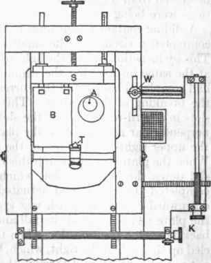
Fig. 32. - Diagram of the adjustable headrest.
S, forehead support; T, tooth rest; B, opaque blind for left eye; K, knurled heads controlling the rack and pinion devices; W, wing nut clamp for fixing the bead-rest in any desired position; A, position of lens or artificial pupil.
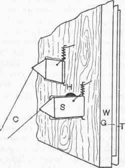
Fig. 33. - Detail of the small shutters and windows in the eye-reaction stimulus apparatus.
S, shutter controlled by cord, C, for opening the 1 cm. holes, H, in the wooden door W; the light thus came to the milk glass, G, and a portion of it passed through the 2 mm. opening in the thin metal sheet, T, the exposed surface of which was painted flat black.
Continue to:
My Books

