


Reaction Time For Turning The Eye To A New Point Of Regard. Part 3
Description
This section is from the book "Human Vitality And Efficiency Under Prolonged Restricted Diet", by Francis G.BENEDICT, Walter R. Miles, Paul Roth, And H. Monmouth Smith. Also available from Amazon: Human Vitality and Efficiency Under Prolonged Restricted Diet.
Reaction Time For Turning The Eye To A New Point Of Regard. Part 3
The circuit of the solenoid, S (figures 34 and 35) was completed by the sliding contact C (figures 30 and 34), as explained in connection with the modifications made in the falling-plate camera. From figure 35 it may be noted that when the solenoid acted, the part designated as 1 was shifted to the left in the picture. This caused the falling of the frame 2 resting on the top of 1. This frame carried the shield A, which interrupted the beam of light until that moment when the falling of this frame turned the photographic light on the eye of the subject and at the same instant completed the circuit in the mercury switch, M.
1In this report our interest is in comparative results. It may, however, be stated that 0.02 second for latency of apparatus should be deducted from the values as printed to reduce them to an absolute basis. This factor was determined from photographic records taken specifically to reveal the constants of the apparatus.
The sequence of events just preparatory to recording an eye reaction was therefore as follows:
(1) The operator grasped some one of the cords leading to the stimulus device and, by gently pulling, opened a window and held it open. The lamp filaments were glowing red in the box behind the milk glass, but did not give off enough light to make it possible for any subject to discover which window was open.
(2) The photographic plate was released. Very early in its fall it completed the circuit for the solenoid. The action of this quick and powerful magnet released the frame designated 2 in figure 35.
(3) The sudden downward movement of the frame and its parts caused the exposure of the eye to the soft blue photographic light, and at the same instant the completion of the short circuit which brought the stimulus light to full brilliancy in the opened window.
Two other cords shown as C in figure 35 were useful in manipulating the apparatus. One was connected with the shield which temporarily interrupted the beam of light from the subject's eye. This could be drawn down for a moment when focusing and finding position. The other was so arranged that, by pulling on it, the frame 2 could be raised into position after a reaction had been taken and thus made ready for another reaction. This lifting of 2 cut off the light from the subject's eye and broke the circuit to the lamps in the house, H. In the photograph made for figure 35, three of the shutters have been opened so as to expose the light, which can be seen at the points near L in the figure. In the center of the field at which the subject looked there was a white fixation mark which always remained unchanged.1 The stimulus openings were arranged on four axes passing through this fixation mark, that is, horizontal, vertical, and at angles of 45°. The points were 2 mm. in diameter and on any axis were arranged 3, 6, and 12 cm. from the central fixation mark. In the four corners of the viewed field there were points which were 15 cm. from the fixation mark. The field was 45 cm. from the subject's eye.

Fig. 34. - Wiring diagram for the eye-reaction stimulus apparatus.
L, four 60-watt Mazda lamps in parallel; R, resistance always in circuit; M, mercury switch for short-circuiting R; C, sliding contact; S, solenoid for operating M.
Explanation Of Figure 35
B. black screen surrounding subject's field of view; H. lamp house of stimulus apparatus; L, general location of stimulus lights; F, a screen carrying a fixation mark and to be folded down over the plane L when eye movement* are photographed; arrows indicate the path of beam of light; 8, a solenoid which, when operated, moves support, 1, to left, causing frame, 2, to fall; 2 carries the shield, A, and a part of the mercury switch, M; thus, its fall lights the lamps to B. producing a stimulus at L, and exposes the eye to the recording light; C, two cords, one for lifting 2 again into position, the second for withdrawing A while the camera is focused.
Explanation of Figure 36
Each line of dole is a rection record. A black dash with one interspace represents 0.01 sec. Counting from the bottom (stimulus) the first definite bend in a line of dots indicates the moment of reaction. e. g., in the extreme left hand record 20 dashes are counted between these points; the reaction time was therefore 0.20 sec The records are from two subjects; those to the toft hand plate show shorter and more regular reactions.

Fig. 35. - A subject in position at the photographic apparatus and ready for the eye reactions.
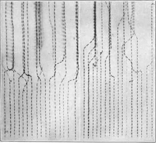
Fig. 36. - Sample eye-reaction records, unretouched, reproduced full size from contact prints of the original plates.
The stimulus device was perfectly satisfactory for our purpose, save that occasionally some one of the shutters would fail to close completely. In the measurements taken in this research and in many others made previously no secondary criteria can be discovered as coming from the stimulus apparatus. A slight sound due to friction can be heard when a string is pulled to open a shutter previous to giving the stimulus for reaction, but this sound is localized, as being behind the lamp house and under the table. In this investigation the inner ring of stimulus positions, that is, those which were only 3 cm. from the fixation point, were not used, nor were the positions vertically above and vertically below the fixation position. This limited the number of stimulus positions to 16, all of which were used with about equal frequency with any one subject.
Sample records of the eye reaction are reproduced full size in figure 36. The light which falls upon the subject's eye is interrupted by a timing vibrator and so causes the photographic record to appear as a row of short dashes. Each dash with one interspace is equal to 0.01 second. The records are to be read from the bottom upwards. When the line of dashes suddenly turns right or left it indicates that the eye of the subject has moved in the direction of the stimulus light. The number of dashes from the beginning of the record to the point where movement begins gives the reaction time. The records illustrated are from two subjects. Those shown in the right-hand plate are seen to be, in general, longer and more irregular than the others.
Continue to:


My Books

