


Brown Dust, Moisture, And Volume Determinator For Blastfurnace And Other Gases
Description
This section is from the "Blast Furnace Construction In America" book, by J. E. Johnson, Jr.. Also see Amazon: Blast Furnace Construction In America.
Brown Dust, Moisture, And Volume Determinator For Blastfurnace And Other Gases
This apparatus has been devised in order to determine accurately the amount of dust and moisture contained in blast-furnace gas, as well as the volume of the gas, and is used with considerable success.
Referring to the accompanying drawing, Fig. 205, A is a gas main conveying the gas to be tested. B is an aperture in the small pipe through which samples of the gas are drawn. C is a filtering medium within which the solid constituents of the gas are deposited. D is a conduit leading to the exterior of the gas main through which the filtered gas is conducted. E represents a flexible connection to a surface condenser, F. G represents a receptacle for some chemical, such as calcium chloride, which can be used for the purpose of taking out the moisture contained in the sample. H is a conduit from this moisture-removing receptacle to the rotary air pump, I, or through the by-pass J to the three-way valve K and thence to the gas meter L, where the volume of the sample is determined, together with its temperature and pressure; these latter by means of the thermometer M and the U-tube AT, respectively. An electric motor, O, is used to operate the pump I through the variable-speed drive P.
"An indication of the velocity of gas or gases in conduit A is transmitted through aperture Q in the sample pipe and conduit R to horizontal pressure gauge S; also an indication of the velocity of gas or gases after passing aperture B is transmitted from aperture T through conduit U to horizontal pressure gauge S. It is evident that changes of the velocity of the gas or gases in aperture B of sample pipe, produced by the suction of pump I or by pressure in gas main A, 8re indicated, and can be accurately controlled and made equal to the velocity of the gas or gases in conduit A, the gas main, such indicator being the oil piston shown in glass tube forming a part of the velocity gauge S.
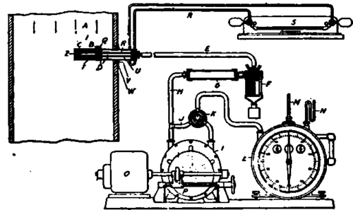
Fig. 205. The Brown dust, moisture and volume determinator.
"The method of operating this apparatus is as follows: The dry weights of the filtering medium C, of the receptacle G, containing the calcium chloride, and of the measuring flask attached to surface condenser F, are very carefully determined. They are then inserted in the apparatus, and the sample pipe is then inserted in the gas main, a tight connection being made between flange W and bushing V. The meter reading is noted. At the same time that the sample pipe is inserted in the gas main A, the time is noted, and the rotary pump / started. The speed is then so regulated that the oil piston in the horizontal pressure gauge S is maintained in equilibrium. This indicates that the velocity in aperture B is exactly equal to the velocity in gas main A, this condition having been determined by a measured amount of gas in gas main A, and the proper proportioning of aperture and conduits in the sample pipe during the calibration tests. This condition is maintained for an indefinite length of time and the sample pipe is then withdrawn from gas main A. The meter reading, multiplied by the ratio of area of aperture B to area of gas main A gives the total amount of gas passing through gas main A in the elapsed time. The difference between the dry weight of the filtering medium C, before and after the test, divided by the number of cubic units shown by the meter, gives the weight of dust per cubic unit. The moisture per cubic unit of gas is found in a similar manner from the sum of the weights of the water in drying receptacle the water caught in the measuring flask attached to surface condenser F, and the weight of water retained in the filtering medium C".
Figs. 206 to 211 are reproduced from Mr. Diehl's paper as showing approved types of construction. The text of Mr. Diehl's concerns itself principally with operation and does not concern us here.
Pig. 206. Duquesne gas-cleaning plant, showing scrubbers, with intake from dirty-gas main and offtake to collecting main; also settling basins.
In addition to the processes so clearly described by Mr. Forbes, there are various others designed to remove the dust from the gas in the dry state, but as these have had no extensive application for the blast-furnace process, they may be omitted here.
Even since the time of Mr. Forbes' paper there has been an extensive development in Europe of the Halberger-Beth process of which there are now almost thirty plants in use in Europe and the number has been rapidly increasing. American furnacemen have been slow to take up this process and have acted in this matter along the same line as in many other cases; where an apparatus requires careful supervision or where its maintenance charges are high, operating economies secured by its use are disregarded. The same has been true in regard to the gas engine, by-product coke oven and many other kinds of apparatus.
This attitude is one often censured not only by foreigners, but also by Americans who do not consider all the aspects of such problems, particularly the financial one. The relative cheapness of capital and supervision and the costliness of raw materials in Europe as contrasted with the high cost of capital and supervision in America and the low cost of raw material constitute no small measure of justification for the American attitude.
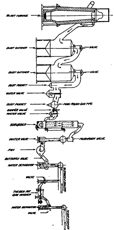
Fig. 207. The course of the gas through the cleaning processes to stoves, boilers and engines.
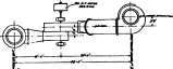
Fig. 209. Section through fans, and method of passing gas through seals and separators.
There is reason to hope that a process may soon be developed superior to either the wet processes or bag filtration plant and less complicated and difficult of maintenance. I refer to the Cottrell process for the electrical precipitation of the dust by a high-tension direct current passing through the gas column. This process has been developed to complete success in several lines of industry but its sponsors have hesitated to attack the blast-furnace problem on account of its size and the complexity of the conditions. If this process is ever worked out to a commercial success it will furnish gas absolutely clean with no loss of temperature and with no increase in its moisture.
These are the ideal conditions for the use of furnace gas for combustion purposes. For the gas engine it must in any event, in present practice, be cooled about to atmospheric temperature, and this, of course, can easily be done by a direct spray after the dust is removed. Perhaps the time might even come, if hot cleaned gas were available, that the gas engine could be adapted to its use and thereby further increase its economy.
Fig. 210. Section through Theisons, seals and separators.
In conclusion it may be said that it is impossible at the present time to write a history of gas cleaning. The whole development of gas cleaning in this country covers barely twelve years in all and nine-tenths of it has been in the last seven or eight years. The advantages have become manifest and all furnacemen have sought a way rather than the way to clean the gas and undoubtedly they were right in this course, for the plants installed early, even though not the last word of perfection in the subject, will have paid for themselves in bettered operating conditions before the much-to-be-desired best method is developed. It is possible, therefore, with this rapid development in progress, only to give an outline of the subject and to state briefly the principles which underlie its application.
Fig. 211. Dirty-gas main with clean-gas main at higher level, also the end of the refined-gas main leading from the Thei-sens to the engines.
Continue to:


My Books

