Inertia Of Reciprocating Parts
Description
This section is from the "Blast Furnace Construction In America" book, by J. E. Johnson, Jr.. Also see Amazon: Blast Furnace Construction In America.
Inertia Of Reciprocating Parts
This is not the place for an extended discussion of the subject of the inertia of the reciprocating parts, which is a mathematical problem of no mean order if it be handled completely and accurately. For our purpose, it is sufficient to say that the inertia of the reciprocating parts at the end of their stroke exert a force equal to the centrifugal force of an equal weight hung on the crank pin, and in the same direction, that is, outward from the center of the crank shaft. Starting at this value at the beginning of the stroke, the inertia diminishes in the same proportion as the distance of the piston from the center of its stroke, at which point the inertia becomes zero. Then, as the piston approaches the other end of the stroke the inertia effect rises from zero to an equal amount in the opposite direction.
It is obvious that this inertia always acts outwardly from the crank shaft; that is to say, at the head end of the stroke it acts toward the head of the cylinder, and at the crank end of the stroke it acts toward the crank end of the cylinder. The fact that this force increases from zero at the center to a maximum at the ends, and then decreases down to the center again on a straight line diagram, should be emphasized because it is often supposed by those who have not studied the subject that this force is exerted only at the end of the stroke. Nothing could be further from the truth.
The statement of the exact proportionality of this force to the distance from the center of the stroke is exactly true only when the connecting rod is of infinite length, or when the slotted cross-head or Scotch yoke is used, which, of course, is never done with blowing engines. With connecting rods of finite length the inertia effect is greater at the head end and less at the crank end than the amount stated, by that fraction which expresses the ratio of the crank-throw to the connecting-rod length. This, while a matter of some importance to designers, is not of sufficient importance for our purpose to necessitate its being taken into account, as the assumption of the straight line diagram for the inertia effect is sufficiently accurate for our purposes.
It will be obvious from what has been said that this inertia effect tends to absorb energy from the steam cylinder in the early part of the stroke, when energy is required to accelerate these moving parts, and to give it out again in the latter part of the stroke, when these parts are being retarded by the movement of the crank. This means that the reciprocating parts are taking up energy at a time when the steam cylinder has it to spare, and giving it out at a time when the air cylinder needs it.
In order to investigate this effect quantitatively in relation to the air and steam pressures, it is necessary to determine the total inertia effect and then consider it as distributed over the air piston as if it were a force of so many pounds to the square inch. Similarly, we can reduce the pressure of the steam cylinder in the ratio of its area to that of the air cylinder, and so put all three of these forces on the basis of a common unit, of pounds per square inch of air-cylinder area.
Through the kindness of the William Todd Co., of Youngstown, I have obtained sets of indicator cards from the air and steam cylinders of steam-blowing engines, and also similar cards from a gas-blowing engine. They have also given me the rated speeds of these engines and the weights of the reciprocating parts, as well as the diameter of the various cylinders and the strokes.
These diagrams for a horizontal cross compound blowing engine with forty-eight-inch high-pressure cylinder, ninety-inch low pressure, ninety-six-inch air cylinders and sixty-inch stroke in common are those shown in Figs. 73, 74, 75, and 76.
These cards were taken to represent approximately simultaneous conditions in all the cylinders. The rated speed of this engine is forty revolutions, the weight of the reciprocating parts on each side is approximately sixty thousand five hundred pounds.
From these I have laid out what may be called the resultant diagrams of all three forces, that in the steam cylinders, that in the air cylinder, and that of the inertia - all reduced to pounds per square inch of air-cylinder area, which are shown in Figs. 91, 92, 93, 94.
There are obviously four sets of such resultant diagrams for such an engine, one representing one stroke in each direction and on each side, but as all of these are more or less similar one will be sufficient to show the principle involved.
We first have to combine the diagrams as taken which represent the conditions throughout the cycle of one revolution in each end of each cylinder and combine them into "net pressure" diagrams for the steam and for the air cylinders by deducting from the pressure in one direction, the simultaneous pressure in the opposite end of the cylinder in the opposite direction, this subtraction being made in the algebraic sense. These two net pressure diagrams are shown in Fig. 91, the pressures of the air diagram being in the opposite direction to those of the steam diagram. Ordinates below the line represent pressure in the opposite direction to that represented by ordinates above the line. We can obviously combine these two diagrams into one by subtracting the ordinates of one from those of the other in the algebraic sense. The result of this operation is shown in Fig. 92, which shows that the pressure is entirely in one direction during one-half of the stroke, and suddenly changes to the other near the middle of the stroke. On this diagram is shown, as a solid straight line passing through the center, the value of the inertia per square inch of air-cylinder area, for forty revolutions, and in dotted lines that for fifty-five revolutions.
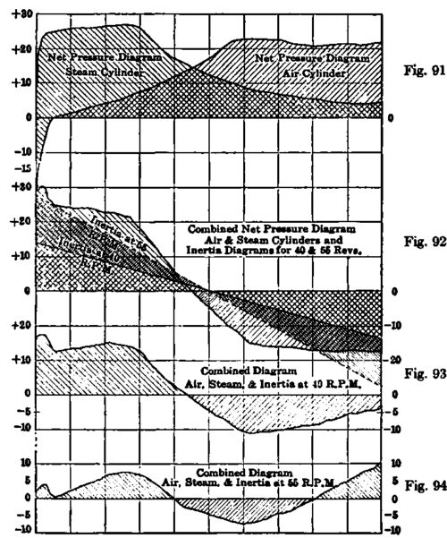
Figs. 91-94. Diagrams, of steam, air, and inertia combined.
Remembering that ordinates of the inertia diagram above the zero line on the left-hand side of the diagram mean energy absorbed, and those below the line on the right-hand side of the diagram mean energy given out, we can obviously deduct these ordinates from the net-pressure ordinates of the combined diagram for air and steam, and the result will be the final net pressure transmitted to the crank pin. The result of this subtraction is shown in Fig. 93 for forty revolutions, while Fig. 94 shows the result which would be obtained on a similar basis if this engine were run at fifty-five revolutions instead of forty.
It will be obvious at a glance that the energy represented by the triangular area of the inertia diagram has been subtracted from the energy imparted to the fly-wheel in one part of the stroke and subtracted from that given out from the fly-wheel in another part of the stroke, the result being that the energy transmitted through the running parts at forty revolutions is only about one-half of that represented by the total work done, and would become an almost insignificant amount at fifty-five revolutions.
It may be thought that these considerations are too theoretical to be of practical importance, but I have seen large blowing engines in poor condition which would make a noise almost like steam hammers when running at a low rate of speed, but which would quiet down when the speed was increased until at a speed as high as the valve gear would stand they would run silently and well. Moreover, the Southwark Company has designed blowing engines on this principle for many years which have run as successfully as those of any other maker, and more successfully than those of some builders, who use much lower speeds because they are afraid of the higher ones.
The Nordberg Manufacturing Company also has built blowing engines, some of them to the specifications of the writer, which were designed on this principle. They had a relatively short stroke, and ran at a high rotative speed, and so obtained the displacement of a much larger engine at a lower speed. These engines were properly proportioned as to the inertia stresses and ran with the most perfect smoothness and absence of all pounding and noise at high speeds, seventy-five and eighty revolutions, as well as at lower ones. These facts have a most important bearing upon the design of blowing engine to be preferred.
Continue to:
My Books

