Forge. Part 4
Description
This section is from the "The Construction Of The Modern Locomotive" book, by George Hughes. Also see Amazon: The Construction Of The Modern Locomotive.
Forge. Part 4
All the hammer blocks have a radius of about two inches at one edge, this being used for all forgings requiring a similar radius or larger; but if smaller, it is set in with a bar. The middles are drawn down to a peg, and the radius B, Fig. 229, is formed by plates. Fig. 228 shows the swages for the enlargement in the centre of the rod for the oil cup, and after the small ends have been drawn down to a peg, the rods are cut to length and sent from the forge ready for the milling machine. Tig. 229a shows the forging for the big end strap, and Fig. 230 in its finished state. A bloom is roughed out to 7 by 4 inches by 3 feet 7 inches, making two straps, one end of which is drawn down to 5⅛ by 3⅛ inches for about 20 inches, and the rest to 3⅛ inches square. The end 5⅛ inches deep is then set down by a tool, as shown in Fig. 229b, to 3⅛ inch square, leaving the oil cup as required, and afterwards the knees B, Fig. 229a, are set in with a fuller for the corners in bending, which operation is performed in the smithy, making use of the block, Fig. 229c. A is a cross-section, and F a plan of this, and it is practically a substitute for the hammer block. The small curved plate B is placed at the bottom of the strap recess at D resting upon C, the function of which is to give the strap good round corners and leave plenty of metal for the smith to work up afterwards, whereas C is simply a convenience for raising or starting the strap upwards by means of a couple of wedges, if it has been wedged by the bending process. The actual bending is accomplished by means of a few blows from the hammer, transmitted through the rectangular block E, and one or two making-up pieces.
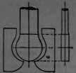
Fig.227.
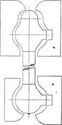
Fig. 227.

Fig. 227 A.

Fig. 229 A.
Fig. 229b.
The little end straps, Figs. 231 and 232, are made in a similar manner from a solid bloom about 6 inches square, drawn down to about 4 inches square, after which the oil cup is struck out by a tool having the following section, and the rest of the strap is drawn down upon each side of the cup to a peg 3¬ by 2« and 2 inches. They are then sent to the smithy in the form of Fig. 231 and afterwards bent. Failing more appropriate tools, or lack of quantity, the sketches Fig. 232a, represent the progress of this operation. The U-piece of iron A is about 2« or 3 inches in diameter, and simply bent to a semicircle, and the forging is placed successively as represented, receiving the shown figure the hammer through a fuller as directed by the crown. After the third representation the forging is ended and receives the blows direct, until it is bent over to nearly the required width, when it is finished exactly by placing a block inside the bend, and then closing by a few more blows, after which it is hammered to thickness upon its edges and pared up.

Fig. 229c.

Fig. 231.
Fig. 232.
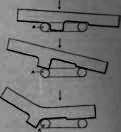
Fig. 232A.
The valve rods and anchor links for Joy's valve motion are made in a similar manner to each other, and are shown in Figs. 233 and 234, and consequently one description of the manufacture will suffice for both, the example given the valve rod, the only difference being in the length bloom is roughed out to 7 by 4 inches, and then drawn to 5¬ by 3¾ inches, the largest dimensions of the end which the middle is drawn down to peg 2¾ by 1¬ inches. Swages, Fig. 233, are used to form the shape of the ends, after which they are worked in the die, Fig. 235, in section, a plan of outline being given in dotted lines in Fig. 234, which leaves them a well-finished job, ready for the machine shop. The radius links for the slipper blocks for Joy's motion, which can be clearly surmised from the blocks used, are made from solid beat iron blooms about 7 by 5« inches by 1 foot 7 inches, requiring the group of tools shown in Fig. 236, when a restricted quantity of links suffice the necessities of the shop, and when it would not pay to roll them in a merchant mill and set them to the required radius afterwards. After re-heating, first operation is to stamp a straight rectangular bar into bloom, making it into a channel, and then follow on with bars 2-5, Fig, 236, which gradually open out the groove. en this rough forging is bent to radius as indicated by D,

Fig. 233.

Fig. 235.

Figs. 236.

Figs. 236.
Fig. 236, and afterwards the bar 6 is inserted, having the exact radius. The forging is then re-heated and stamped into the blocks E, and afterwards the fins and flashes removed as indicated by C, Fig, 236, then sawn to 16⅜ inches long ready for the machine shop.
Fig. 237.
Fig. 238.
Fig. 238 a.
The stirrup link, Figs. 237 and 238, is at present chiefly smithy work, and is produced from a forging 4 by 3 by 14 inches, being first of all smithed out to Fig. 239; A being about 2« inches high, B to finish forge dimensions, utilising the clapper swages, Fig. 238a. Two similar forgings are prepared, then firmly welded together, and afterwards dressed up. The swing links, Figs. 240 and 241, are worked from forgings 4¬ by 10« by 20 inches, being first set down in the middle and pared off or finished in clapper swages. The valve buckles, Fig. 242, are forged from wrought-iron piles of about 2 cwt. in weighty which are shingled at a welding heat into blooms about 7 by 3 inches. These blooms are re-heated and roughed out under the hammer, being drawn down by the aid of plating tools, and the shanks are roughly rounded to peg. Afterwards the ends A and B, Fig. 242, which is the finished forging, are stamped in bored blocks 1¾ inch for the dummy gland end. Fig. 243, and 2 7/16 by 6 inches long for the welding or spindle end, Fig. 244, which jumps them to fill the hole, leaving ¬ inch on for turning at the short end, and ample metal for scarfing and welding at the opposite end. They are made in pairs in the forge, and finished in the smithy. They are received by the smith generally as in Fig. 244a, but occasionally, when the forge is hard pressed, one or two may be sent as indicated by the dotted lines. The first operation then, is to draw out the ends under the hammer, and at the same heat stamp them again in the blocks which set the taper. Afterwards the ends are again thinned by a plating tool. Each portion is bent by the aid of the tool A, Fig. 244B, the shank B fitting into the square hole at the flat end of the anvil. After each portion has been bent it is scarfed for welding, Fig. 244c. The spindle is then welded on and the whole set to template, ready for the machine shop.
Fig. 239.
Fig. 240.
Fig. 242.
Fig. 243.
Fig. 244.
Fig. 244a.

Fig, 244b.

Fig. 244C.
Continue to:
My Books

