The Foundry. Iron. Part 5
Description
This section is from the "The Construction Of The Modern Locomotive" book, by George Hughes. Also see Amazon: The Construction Of The Modern Locomotive.
The Foundry. Iron. Part 5
When the cylinders are not moulded from iron patterns on a machine, the following method may be taken as an example: - The top half or steam chest portion is placed at the bottom, in order to get all the steam passages and valve faces perfectly clean. Place the joint of the pattern K, Figs. 53-56, upon a "turnover board," which in this case is an iron bed-plate on the floor level, and line up with facing sand; pot on the middle box, and ram up with backing sand. Vent all round with 5/16-inch or ⅜-inch vent wire, placing «-inch iron in front of the leaders L, Figs. 58 and 60, to strengthen and prevent the metal breaking into the mould. Gaggers, like loose irons, are placed between the body core prints, to bind the mould at this point; also between each of the webs M, Fig. 53, the valve rod core, and in front of the blast pipe seating N, Figs. 53 and 58, N', Fig. 53, being loose formers, which remain in the mould when the pattern is drawn, and afterwards removed. A shallow groove is also formed and filled with cinders at M, Figs. 53, 57, 58, and a ⅜-inch vent wire is pushed down to the foot of each gagger, An angle-iron is used sometimes at this joint to strengthen it. Parting sand is then sprinkled upon the core prints and joint, the bottom box placed on, rammed up and vented all over, no gaggers being required in this box. This portion of the mould is then turned over, placed in the pit, and the joint made good and solid; that is, although it has been rammed from the opposite side, it is tested all over to find the weak places. The other half of the pattern P, Figs. 54-56, is then placed in its dowels, lined up with facing sand, the top box put on, gaggered, rammed up with backing sand, and vented all over as indicated in Fig. 57. The top box is then lifted, turned over, and the pattern drawn, using the crane straight away to separate the middle from the bottom, drawing the pattern from the middle.
When the middle box is separated from the bottom it leaves the steam chest core prints, the core N, Fig. 58, and the loose formers N', Fig. 53, so that each portion of the mould can be easily got at and finished, making good all portions disturbed by drawing the pattern, and then fin, as little as possible consistent with a risk of crushing, as a fin is always preferable to a crush. Sleak over with blacking, which gives a gas-evolving, or kind of spheroidal coat, and protects the metal from the chilling effect of the sand, Place the middle box upon the bottom, and fix the two side cores, Figs. 57 and 60, by the bolts b. The core irons, vents and "rickets," by means of which the gases strike away through the bolt holes b are clearly shown, and this remark will suffice for all side and lightening cores. The moulds are then well dried; afterwards the bottom portion is separated, and the team chest cores fixed, S, Figs. 57 and 59, making good all round the joints of the prints, these cores being held down by bolts to the bottom of the box. The drain chamber core is then fixed upon four studs T, Fig. 58, which by means of two 1⅛-inch round cores, form a communication between the two steam chests, and further by means of the cores T', Figs. 58 and 60, with the pet cocks. The S and exhaust cores are then fixed and all joints made secure; Figs. 57 and 59 showing them in position secured by the bolts b, the vents in the S cores being formed by a straight wire and joined at the curves by a piece of string, the gases striking through the holding-down bolts. Place the steam chest cover core in its recess V, Fig. 59, and drop the middle box upon the bottom, then carry the core V1, Fig. 59, forward, making the back good with sand, fix in the vent pipe W, Fig. 59, which enters the cinders of the steam chest core S.
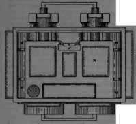
Fig. 53.
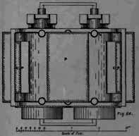
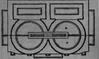
Fig. 55.
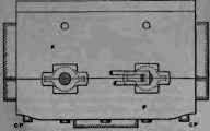
Fig. 56.
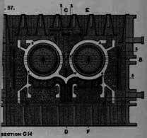

Fig. 58.
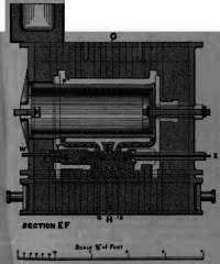
Fig. 59.
Then well stop up the joint between the two boxes with loam, and place the valve spindle cores X, Figs. 58-9, the prints for which have been formed by pocket cores, and loam the joints of these up. This portion is then placed in the drying stove again for twelve hours and afterwards placed in the pit, the sand of which has been lightened up and sprinkled with hay. The centre shaping core Y, Figs. 57, 58, 60, is then placed upon studs. There is generally about 3/16 inch space between this core and the top shaping core, which is made up with loam to prevent crushing, the gases from this core being conveyed by the ⅜ - inch vent holes Y', Figs. 57, 58 and 60, from the cinders in the bottom core to those in the top. The two body cores are then fixed, and the whole passed by the foreman. The boxes and body cores are then cottered up, and joints made secure with loam, especially at the fin F', Fig. 59. It will be observed that there are not any feeders or risers beyond the leader, and these have not been found to be necessary, the head of metal in the basin over the leaders being quite sufficient. By means of the core prints C P, Figs. 54 and 56, and the core Z, Fig. 57, these patterns can be utilised for another class of engines, having a leading bogie.
Fig.60.
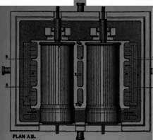
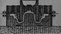
Fig. 61.
Scale 1 1/2" = 1 Foot.
Fig, 61 shows the method of casting the covers, and Figs. 62 and 63 the front and top steam chest covers, the two latter being examples of plate moulding, the core in Fig. 62 being shown in dotted lines. Fig. 64 is the piston head, and when a moulding machine is not used, Fig. 65 shows the method of easting barrels for the piston rings in the foundry floor.
Continue to:
My Books

