The Foundry. Iron. Part 7
Description
This section is from the "The Construction Of The Modern Locomotive" book, by George Hughes. Also see Amazon: The Construction Of The Modern Locomotive.
The Foundry. Iron. Part 7
The metal in these castings being so thin, great care must be exercised or many will be lost in contraction, For this reason the cores contain more cinders than usual, especially the sand-box, where the metal completely surrounds it, and the core irons, which are generally covered with loam to the depth of 1 inch, are in this case covered to a depth of 2 inches, thus enabling the cores to give with the contraction. When the splashers are cast alone, a green sand core may be used.
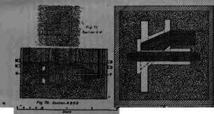
Fig. 72.
Fig. 72 is a section through the joint of the valve-box, which is attached to the above sand-box. It is run by means of a ¾ inch gate on one flange and a ⅝ -inch riser on the other. Fig. 73 is a transverse section of the chimney through the smoke-box. It is moulded from two iron patterns, that from the seating on the smoke-box to the core joint forming one portion, and from the core joint to the top the other. The bottom core print of the latter enters a socket, which is part of the bottom box. The first operation is to line up this socket with facing sand, and then drop the bottom portion over, firmly bedding it down, and ramming it up on the inside. The second box is then placed in position, and the pattern for the chimney fixed in. The gaggers are then put in this box and rammed up, a layer of cinders being placed at the joint with the third box, which is not broken after the third and fourth boxes have been rammed up, the joint proper being at the top of the coping, which has to be broken to draw the pattern. There is one circle of ⅜ - inch vents round the top, which meet the needle vents under the coping. The core is struck up, and consists of one round of hay band tightly bound to the barrel, with one thin layer of clay to stick the loose straws down, and one coating of loam. It is then thoroughly dried. Afterwards the finishing coat of loam is put on and the recess at the coping made. The core barrel rests upon the iron of the core print at B to prevent crushing, a little parting sand being Sprinkled on the joint to keep the metal from bursting in. The casting is poured from the two points A, the metal entering the mould by three branches from each gate, a riser being upon the opposite side.

Fig. 73.
The moulding of the blast or exhaust pipe is shown in section, Fig. 74, and in plan, Fig. 75. This method is adopted in cases where a foundry is short of moulding boxes. To use a bottom as well as a top box is the better plan, as it facilitates the work. In this case the foundry floor must be prepared, the pattern firmly bedded in, and the position of the top box secured by stakes or angle irons. The casting is run by means of the inch gate C, and an inch riser R. The necessity for venting is not very great, the body of metal being small, the only provision being for the air to strike away from the core as shown by the arrows, Fig. 74.
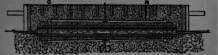
Fig. 74. Section A B.

Fig. 75.
In Figs. 76, 77 and 78, is clearly shown the method of casting the fire-bars on a plate pattern, the angle irons at the corners of the box being guides for the plate. It is a very quick and trustworthy method, the wasters being extremely few. In Fig. 79 is seen a half-size transverse section of the plate pattern, showing the bar cast on flat with a slight inclination, by means of which whatever small quantity of dirt goes over with the metal, rises to the least important part of the bar. This also causes the least amount of sand to be lifted in the top box, and the least risk of disturbing the mould when drawing the pattern. Small bars may be cast vertically, and three or four on one plate.
Fig. 76.
Fig. 77.
Fig. 78.
Fig. 79.

Figs. 80 and 81 are sections of the axle-box keep, the box itself being either a, steel or a brass casting. They are top poured, the metal entering the mould by two branches from one gate, a riser being upon the opposite side.

Fig. 82.
Fig. 83.
Figs. 82 and 83 are sections through the; tender axle-box.
Fig. 84.

Fig. 85.
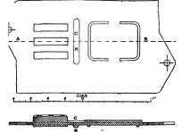
Fig. 86. Section A B.
They are cast by means of a ¾ - inch gate at C, to one of the flanges or horn-block guides, and a ⅝ - inch riser at R. The core is bound together by loose irons, as distinguished from a regular core iron, and straight vented with needle vents, the mould being also vented at the sides and bottom. Figs. 84 85 and 86 are the plate patterns for the front lid of the tender axle-box, and the packing or making-up piece between the top of the box and the brass, C R being connecting runners or gates which are formed when the pattern is made, by the moulder scooping out the sand with his trowel.
As nearly one hundred patterns are required for iron eastings for a locomotive, besides steel and brass, it can easily be surmised that these illustrations might be carried on to a greater extent, but the author considers the examples given as fairly representative of iron foundry practice, and to carry them further would simply be a protracted use of the terms "line up with facing sand," "ram" and "vent."
Continue to:
My Books

