Reinforced Concrete. Part 6
Description
This section is from the book "The Building Code Of The City Of Boston", by City of Boston Building Department. Also available from Amazon: Building Code of the City of Boston.
Reinforced Concrete. Part 6
Stress in Concrete
Par. 100. For determining the stress in concrete due to the bending in each strip the width shall be taken as the width of the strip, except that for negative bending in A-strips when a dropped panel is used the width shall be that of the dropped panel.
Par. 101. - Wall Beams. - Wall beams in flat slab construction shall be assumed to carry a width of floor equal to one quarter the clear span of the beam in addition to the weight of beam and wall. Such beams, when continuous, shall be designed for a negative bending at columns equal to - and the positive bending at mid-span shall be assumed as follows: -
Par. 102. - (a) When the width of the columns (parallel to the beam) is not less than fifteen per cent of the distance, centre to centre, of columns or twice the depth of the beam,
M=wl2/20 Par. 103. - (6) Otherwise,
M=wl2/16 Par. 104. - Brick Walls. - In case a flat slab is supported by a brick wall, the wall shall in general be four inches thicker than the minimum thickness otherwise required by this act, or have equivalent pilasters.
Formulas for Reinforced Concrete Construction
Par. 105. - These formulas are based on the assumptions and principles given in section fifteen.
1. Standard Notation.
Par. 106. - (a) Rectangular Beams.
The following notation is recommended:
fs = tensile unit stress in steel;
fc = compressive unit stress in concrete;
E8 = modulus of elasticity of steel;
Ec = modulus of elasticity of concrete;
M = moment of resistance, or bending moment in general; As = steel area;
b = breadth of beam;
d = depth of beam to centre of steel;
k = ratio of depth of neutral axis to depth, d;
z = depth below top to resultant of the compressive stresses;
j = ratio of lever arms of resisting couple to depth, d. jd=d - z=arm of resisting couple;
p = steel ratio = - As bd
Par. 107. - (6) T-Beams. b = width of flange; b' = width of stem; t = thickness of flange.
Par. 108. - (c) Beams Reinforced for Compression. A' = area of compressive steel;
p' = steel ratio for compressive steel; fs' = compressive unit stress in steel;
C = total compressive stress in concrete;
C' = total compressive stress in steel;
d' = depth to centre of compressive steel; z = depth to resultant of C and C'.
Par. 109. - (d) Shear, Bond and Web Reinforcement. V = total shear;
V" = total shear producing stress in reinforcement; v = shearing unit stress; u = bond stress per unit area of bar;
o = circumference of perimeter of bar; ![]() o = sum of the perimeters of all bars; T = total stress in single reinforcing members; s = horizontal spacing of reinforcing members.
o = sum of the perimeters of all bars; T = total stress in single reinforcing members; s = horizontal spacing of reinforcing members.
Par. 110. - (e) Columns.
A = total net area; As = area of longitudinal steel; Ac = area of concrete;
P= total safe load.
2. Formulas. (a) Rectangular Beams. Par. 111.- Position of neutral axis,
(1)
Par. 112.- Arm of resisting couple,
j = l-----k..................(2)
3 [For fs = 15000 to 16000 and fc = 600 to 650, j may be taken at 7/8.]

Fig. 1.
Par. 113. - Fiber stresses, fs=M/Asjd =M/pjbd2 ................(3)
Par. 114 -
fc=2M/jkbd2 = 2pfs/k .................(4)
Par. 115. - Steel ratio, for balanced reinforcement,
p = 1/2 .1/fs/fc(fs/nfc+1)....................(5)
(b) T-Beams.
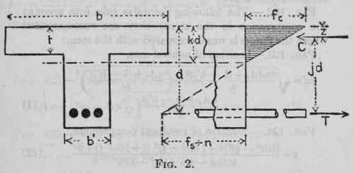
Par. 116. - Case I. When the neutral axis lies in the flange, use the formulas for rectangular beams.
Case II. When the neutral axis lies in the stem.
The following formulas neglect the compression in the stem.
Par 117. - Position of neutral axis, kd=2ndAs+bt2/2nAs+2bt................(6)
Par. 118.- Position of resultant compression, z 3kd-2t /2kd - t. t/3 .................(7)
Par. 119.- Arm of resisting couple, jd=d-z....................(8)
Par. 120.- Fiber stresses, f3 = M/Asjd...................(9)
Par. 121 - fc = Mkd / bt(kd - 1/2t)jd = fs/n. k/1 - k............ (10);
(For approximate results the formulas for rectangular beams may be used.)
Par. 122. - The following formulas take into account the compression in the stem; they are recommended where the flange is small compared with the stem:
Par. 123. - Position of neutral axis,
b' ............. (11)
Par. 124.- Position of resultant compression,
z = (kdt2 - 2/3t3+\ (kd -t)2 (t+1/3(kd-t) ) b'
t(2kd - t)b + (kd - t)2b' ..... (12)
Par. 125. - Arm of resisting couple,
jd=d - z.................(13)
Par. 126. - Fiber stresses,
fs.= M/Asjd..................(14)
Par. 127. -
fc = _________2Mkd_________
[ (2kd-t)bt + (kd - t)2b']jd ......... (15)]
(c) Beams Reinforced for Compression.
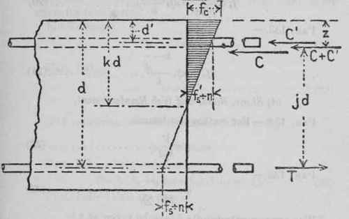
Fig. 3. Par. 128.- Position of neutral axis,
Par. 129.- Position of resultant compression,
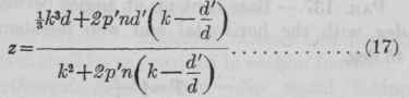
Par. 130.- Arm of resisting couple,
jd = d-z................(18)
Par. 131.- Fiber stresses,
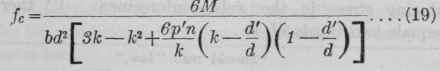
Par. 132. -
fs = M/pjbd2 = nfc 1-k/k.........................(20)
Par. 133 -
k - d' - d
f8' - nfc k - d'/d / k.................(21)
(d) Shear, Bond, and Web Reinforcement. Par. 134. - For rectangular beams,
v = v/ bjd...................(22)
Par. 135 -
u = v /jd. 0................(23)
[For approximate results j may be taken at 7/8-.]
Par. 136. - The stresses in web reinforcement may be estimated by means of the following formulas: Vertical web reinforcement,
T = v's /jd...................(24)
Par. 137. - Bars bent up at angles between 20 and 45 deg. with the horizontal and web members inclined at 45 deg.
T = 3/4 V's/ jd...................(25)
Par. 138. - In the text of the report* it is recommended that two thirds of the external vertical shear (total shear) at any section be taken as the amount of total shear producing stress in the web reinforcement. V therefore equals two thirds of V.
8*Should read "law."
Par. 139. - The same formulas apply to beams reinforced for compression as regards shear and bond stress for tensile steel.
For T-Beams,
v = V/ b'jd..................(26)
Par. 140 -
u = v /jd.0.................(27)
[For approximate results j may be taken at 7/8.]
(e) Columns. Par. 141. - Total safe load,
P = fc(Ac+nAs) =fcA(1 + (n-1)p).......(28)
Par. 142. - Unit stresses,
fc= p / A(1 +(n-l)P).............(29)
Par. 143 -
fs = nfc..................(30)
[1918, c. 179, sect. 5, Special Act.]
Continue to:
My Books

