Part III. Methods Of Sewage Disposal
Description
This section is from the book "A Working Manual Of American Plumbing Practice", by William Beall Gray, Charles B. Ball. Also available from Amazon: Plumbing.
Part III. Methods Of Sewage Disposal
The fact that no specific gas peculiar to sewers and drains is known, and that the analysis of air taken from the interior of soil pipes has sometimes shown fewer germs capable of producing specific diseases than air taken from the room in which the pipes were situated, affords no reason for abating the effort to exclude drain, sewer, and soil-pipe air from buildings. In cities, the public sewers offer fixed conditions of sewage disposal; but where no public sewer is constructed, there are still a number of ways to handle the sewage from house sewers, and there are but few locations that do not offer at least one chance of settling the question in an unobjectionable manner.
For house disposal, irrigation, the dry-and-wet well plan, streams, and dry ravines are among the means most likely to be available. The septic tank, too, while its principles have as yet been employed only to a limited extent for individual houses, bids fair to come into extended use in the future.
The first cost of the garden irrigation plan is greater, usually, than that of other methods; but it has the merit of fertilizing the soil to some extent as a return for the expenditure. The solid matter must be carted away from time to time. The plan consists essentially of buried lines of irrigating pipe ramifying through the ground to be improved, and a specially formed receiver into which the house pipe leads and from which the irrigating lines are supplied, generally by intermittent siphonage. The solid matter subsides; and when a sufficient body has accumulated, the liquid is siphoned without personal attention. Fig. 137 shows the grease trap and siphon well of a garden irrigation plant. The chambers may be of concrete, or of brick laid in cement mortar and plastered. KK are iron cistern-covers with loose tops. The inlet pipe E from the house, has a hole in the crown of the bend, to prevent it from becoming air-bound when the well is full. D is the overflow to the siphon chamber, through which flows a quantity of sewage corresponding to that which at any time enters through the pipe E. B is a hood with notched bottom, placed over the central weir A. The contents of the siphon well rise through the hood, and pour over into A from all points, producing suction, which, with the aid of the tortuous outlet of A, causes periodical siphonage of the liquid down to a level below the teeth of the hood. C is a cone of wire mesh to protect B from becoming accidentally choked. 6? is an air-pipe with strainer at top; H, an air and overflow pipe combined; and J, the vitrified pipe main to the irrigating lines.

Fig. 137. Grease Trap and Siphon Well of a Garden Irrigation Plant..

Pig. 138. Sectional Elevation and Plan of Cesspool for Septic Treatment of Sewage..
The irrigating lines are small, hubless, perforated tile arranged to accomplish, by means of tight headers properly inclined, as nearly as possible an even distribution of the liquid. This device - if properly constructed, and if placed at a suitable distance from the house, in such a position that it cannot contaminate a well or other source of water supply - can be used with comparative safety. Special care should be taken in its construction; and when in use, it should be regularly cleaned.
The slope of the ground necessary for the discharge of a siphon, generally meets the requirements of a better process - namely, the so-called Septic. The cesspool, shown in Fig. 138, is intended for this class of installation. It consists of two brick chambers, the larger having a clean-out opening in the top, provided with a tight cover. A vent pipe is carried from the top to such a height that all gases are discharged at an elevation sufficient to prevent nuisance from their presence. The smaller chamber is connected with the first by means of cast-iron soil-pipe, and is arranged to feed the lengths of porous tile radiating from the bottom, as shown in the plan view. The second chamber thus acts in lieu of the "tight headers" mentioned in connection with Fig. 137. The house drain connects with the larger chamber, which fills to the level of the overflow; then the liquid portion of the sewage drains over into chamber No. 2, and is absorbed through the porous tile branches. The solids, which are small in amount in a properly designed chamber, remain in No. 1, and may require removal from time to time. Unusual dilution and other favoring causes often produce more or less septic action in the second chamber. The intercepting trap may or may not be placed in the house drain.
Some natural, dry ravines are so formed and located with reference to the general surroundings as to offer little objection to their use as points of discharge for the house drain.
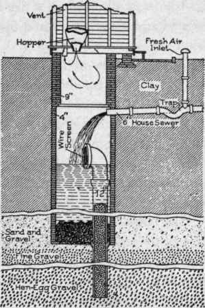
Fig. 139. Sectional Elevation of Dry-and-Wet Well..
Streams should not be employed, unless they are of considerable size and have a constant flow, so as to accomplish sufficient dilution, unfailing throughout the season.
Near the urban limits, acreage available for disposal areas is small, and the land features and general environment so unfavorable that a dry well may sometimes be resorted to. This, in its best form - like the irrigation receiver - separates the solid from the liquid matter, and discharges the overflow of liquid, without much attention, into a stratum of ground in which certain bacterial processes take place. Fig. 139 is an elevation of a dry-and-wet well, which, when properly designed and installed, should operate through a long period without attention.
When the dry-well feature is added to an old vault, it is first necessary to connect the house sewer with the vault. The dry well consists of a 10 or 12-inch tile pipe extending to the gravel stratum and filled with broken rock. This pipe is made water-tight, both where it passes through the bottom of the vault, and within the vault as well. A heavy, grayish scum collects on the surface of the sewage, and indicates septic action. The liquid constantly flows over into the dry well, and some solid matter settles to the bottom.
Continue to:
My Books

