The Making Of Calked Joints
Description
This section is from the book "A Working Manual Of American Plumbing Practice", by William Beall Gray, Charles B. Ball. Also available from Amazon: Plumbing.
The Making Of Calked Joints
In working cast-iron soil-pipe, frequent cutting, as it is termed, is necessary. To do this, all that is required is a hammer, and a cold chisel not too sharp. Make a line around the pipe as a guide, to insure making the piece the same length at all points. Then begin with hammer and chisel, pointing the chisel straight toward the center of the pipe and striking it quick, moderate blows, moving the chisel a little forward on the line after each blow, so as to make a continuous dent all around the pipe. Continue working in the dent until the pipe falls apart. The separating of soil pipe in this way is not a cutting process at all; it is simply packing the iron down in a line until the fiber of the iron is disturbed entirely through the wall, or at least sufficiently to wedge the pipe apart. Where the chisel strikes, the force tends to make the pipe longer, and the strain thus produced wedges it asunder.
Tools Used in Making Calked Joints. Fig. 249 is a yarning tool, the blade being long and thin in order to reach the bottom of the hub. The offset in the handle is to keep the hand out of the way of the pipe when using it. The calking tool is of the same pattern, with shorter blade and heavier. For calking and yarning joints standing close together or in a corner, special forms are needed. The corner tools, as they are called, are offset twice - once to keep the hand free of the pipe, and once edgewise, throwing the blade out of alignment both ways. The offset part next the blade is curved to the arc of the largest pipe it is to be used on, so that the blade will reach down in the hub vertically at the back of the joint, while the handle stands free in the open space for manipulation with the hand or hammer. These tools are necessarily made right and left, as shown in Figs. 250 and 251.
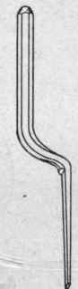
Fig. 249. Yarning Tool..
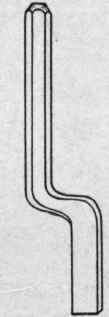
Fig. 250..

Fig. 251..
Right and Left "Corner" Tools for Calking and Yarning.

Fig. 252. Right and Left Calking Tool..
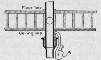
Fig. 253. Use of Special Tool in Calking Joint near Ceiling..
Another form of right and left calking tool is shown in Fig. 252, for use in finishing the joint as described in connection with Fig. 190.
Joints near the ceiling or in other positions, sometimes have to be made in places where regular tools cannot be used. The application of a special tool for the purpose is shown in Fig. 253, b being the hammer face, which is in position to use the hammer on quite conveniently. The hammer end A is made extra heavy, not only to prevent losing the force of the blow by vibration, but to give it weight in making effective jerking blows with the hand when pulling the yarn in.

Fig. 254. Asbestos Joint-Runner, Open and Closed..
Fig. 254 illustrates a joint-runner made of square asbestos rope, with hinged clamp and thumb-screw attached for holding it in place.
There are other forms made that are just as good. These are used in running horizontal and oblique joints on cast-iron soil-pipe work. A fire-clay roll, formed about a strong cord by hand and used just damp and soft enough to bend and pinch in place, answers the purpose very well, though the weight of the lead, aided by steam bubbles formed from the water in the clay, sometimes blows them loose and imposes on the plumber the hard task of getting ready to re-run the joint, to say nothing of the time lost.
Continue to:
My Books

