Piloted Multiple Turning Tool For Steel Gear Blanks
Description
This section is from the book "Boring, Recessing And Multiple Turning Tools", by Albert A. Dowd. Also available from Amazon: Boring, recessing and multiple turning tools.
Piloted Multiple Turning Tool For Steel Gear Blanks
The automobile jack-shaft gear blank shown at A in Fig. 6 is of alloy steel and it is held in special chuck jaws so that it can be drilled, turned and faced simultaneously. A special tool-block on the cut-off slide performs the latter operation, while the turning and drilling tools are carried by the turret. The body of the turning tool V is made of cast iron and is fastened to the dovetail turret face by the gib shown at U. The tool-block K is of steel and is slotted to receive tools M and N. An oil groove is cut at L along the top of the block and it is supplied with oil from the special piping system shown. The pipe 8 leads to the distributing collar T which, in turn, is connected with the cutting lubricant piping system on the machine. The slots in the tool-block are of sufficient width to permit an ample supply of fluid to run down and reach the cutting ends of the tools, thus assisting greatly in prolonging the life of the tools and also allowing higher cutting speeds. The oil-drill Q is held in a steel supporting bushing P which fits the body of the tool-holder. It is supplied with lubricant through the hole R which is connected to the piping system. The steel pilot G is shouldered at H and is forced into the body of the holder. The small hole J is put in so that air pressure will not be generated when the pilot is pressed into place, as this would tend to deceive the fitter by making him think he had a good fit when, in reality, it was compressed air that made the pilot hard to force in. Pilots are sometimes fitted so that they were apparently all right at the time when the work was done, and yet when the time came for the tools to be used, it was found that they were loose enough to cause trouble. The air hole will prevent trouble of this kind.
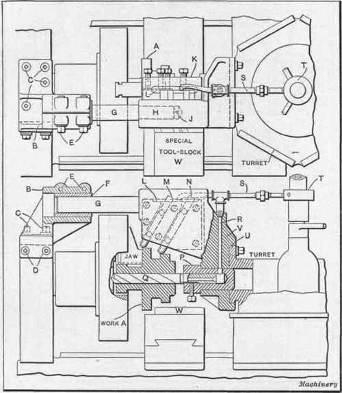
Fig. 6. Piloted Multiple Turning Tool for Gear Blanks.
A special bracket is shown at B and it is screwed to the spindle cap by the screws C and D. The bronze bushing F receives the end of pilot G, and it is clamped by the binding screws E. This method of supporting a turning tool is very successful and assits greatly in permitting heavy cutting without chatter. Another feature of this tool is the manner in which oil is conveyed to the cutting tools. Attention is also called to the position of the tool-block, this being at the rear of the body so that the thrust of the cut is brought directly against the heavier part of the casting. The method of mounting the tools is also a little out of the ordinary, in that the block and tools form a unit which can readily be removed, permitting the substitution of another block with tools arranged differently, to handle other work requiring different spacing. Two turning tools on opposite sides of the turret were used for this particular piece, one being used for roughing and the other for finishing.

Fig. 9. Multiple Turning Tool equipped with Pilot and Holler Back-rest.
Continue to:
My Books

