Coffer-Dams, Shoring, And Strutting. Continued
Description
This section is from the book "Elementary Principles Carpentry", by Thomas Tredgold. Also available from Amazon: Elementary Principles Of Carpentry.
Coffer-Dams, Shoring, And Strutting. Continued
310. Fig. 93 shows a form of dam which was used in 1849 for shutting off the sea from the southern end of the Sunderland Docks, with the view of permitting a further extension of the dock if required.
Fig. 93.

This dam, which is well adapted for d half-tide dam, was constructed inside of a temporary barrier which had been erected to keep out the water while the site of the dock was being excavated. The thickness of the dam was 8 feet at the top and about 16 feet at the bottom, the total height being 28 feet It was formed with guide piles of whole timbers at intervals of about 9 feet, to which the walings were bolted, and the intermediate spaces between the guide piles were filled in with sheeting piles of half timbers 12 inches by 6 inches. "The dam was designed so as to allow the timbers and vertical sheeting to be drawn without running off the water from the dock, and the interior clay to be taken out by dredging. The piles and sheeting were secured to sills laid in chases cut in the rock, strutted to it at the bottom, and tied to it by iron rods, with split lewis bolts at the top; the former, with the view of removing it and the adjacent rock at a subsequent period, and the latter to guard against the pressure of the earth forcing the upper part of the dam towards the dock before the admission of the water, and afterwards, if the water should by any necessity be reduced to a lower level than, usual." *
Wooden struts were used in the body of the dam, but they were arranged so as to interfere as little as possible with the packing of the puddle.
311. The foundations for piers and other detached works under water, when the site is rock, can be prepared at less cost by means of the diving-bell and diving-dress than by a coffer-dam; but cases frequently occur, as in the erection of wharf walls and similar works, where a coffer-dam is desirable. A simple arrangement for constructing a cofferdam on rocky ground covered by water was adopted by Mr. David Stevenson in 1839, for works in the river Kibble.
Fig. 94.
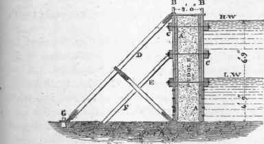
Fig. 94 shows the principle on which this dam was constructed. It consisted of two rows, 3 feet apart, of Memel planks, A, A, 3 inches thick, placed horizontally and held in their places by iron rods, B, B, 2 1/2 inches diameter, which were inserted in the rock at intervals of 3 feet apart in each row. The two rows of rods and planking were tied together by transverse bolts passed through the body of the dam, and fixed to horizontal waling pieces C, C, 10 inches by 6 inches, placed on the outside of the vertical rod.
* ' Min. Proc. Inst. C. E ' 1855-56.
The dam was strutted entirely on the inside by rows of strong struts, D, E, and F, placed 18 feet apart, to avoid interfering with the navigation of the river. The outer stay D (Fig. 94) had eyes made of iron fixed at each end to enable it to be dropped over the upper end of the vertical rod at the top of the dam, and over a pin inserted in the rock at the lower extremity G. A cottar at the upper end kept the stay secure. The counter-stay F was fixed at its lower end by the vertical rod of the dam passing through an eye on the end of the stay, similar to that at G. The other end was strapped to the stay D, which it kept quite secure.
A sluice was placed in the dam at the level of low water to enable the water to be let in should a sudden rise of the river endanger the stability of the dam.
The space between the rows of planking was packed with puddle in the usual way.
The mode of fixing the iron rods is thus described by Mr. Stevenson: - " A jumper point was first worked at the end of each, they were then successively jumped into the bed of the river to depths varying from 12 inches to 18 inches, according to the soundness or hardness of the rock; no other method of fixing was used: the planks of the lower tier were then secured to the iron rods by clasps of iron, and slipped down into their places one above the other. The under-edge of the lowest tier of planking, the fitting of which often occasioned much trouble, was cut previously to being put down, as nearly as possible to suit the inequalities of the rock. The plank was then lowered to its place, and a small iron rod with a hooked end was used for finding what parts did not touch the rock; this having been ascertained, the plank was again raised and the operation repeated as often as necessary, until it fitted tolerably close. The edge was then cut with an adze in a bevelled or wedge form, and the plank being finally lowered, was beaten down by blows from a heavy mallet upon an upright piece of wood resting on the upper edge of the plank. This sharp edge yielding to the blows filled the smaller inequalities of the rock which formed with the puddle a perfectly water tight joint.
"The planks above low water had no fixture to the iron rods, and were kept in their places simply by the pressure of the puddle in the inside of the dam.
"In removing the dam, the puddle was first taken out, and the rods being moved to and fro, could generally be raised after a little trouble." *
312. One of the best examples of a coffer-dam to resist a great head of water is that shown by Plate XXXIX., which was used by Rendel in the construction of the dock at Great Grimsby, commenced in 1848. Its length was about 1500 feet, 300 feet of which were straight, and the remainder formed in two circular arcs of 150 and 800 feet radii respectively, the convex side being towards the river. The depth at low water was from 4 to 10 feet, and the rise of the-tide 24 feet 6 inches.
Plate XXXIX.
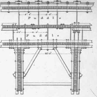
TRANSVERSE SECTION.
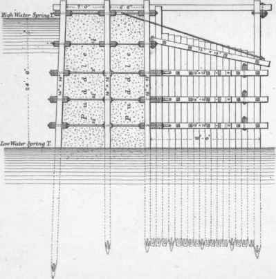
PLAN.
The dam consisted of three rows of whole timber sheet piling, of Baltic yellow pine, from 13 inches to 15 inches square; the outside row battered half an inch per foot, and the other two rows were upright. The sheeting was all driven between gauge or bay piles, placed 10 feet apart. The three last piles driven in each bay were accurately sawn to a taper, in opposite directions, so as to wedge the remaining piles of the bay closely together. The average length of the piles in the first row was 55 feet, and in that of the other two rows 45 feet, though many of them exceeded 60 feet in length.
* ' Trans. Inst. C. E.,' vol. iii. 1842.
The height of the piles above the ground was from 28 to 30 feet, all being driven down sufficiently far to enter a bed of hard clay. The width between the first two rows of piling was 7 feet, and that between the centre and back rows was 6 feet. The front and back rows of piling were secured by five tiers of whole timber double walings; but in the centre row, the three lowest tiers of waling were replaced by bands of wrought iron, 6 inches broad by 1 inch thick, keyed together in lengths of 12 feet, and forming a continuous tie on each side of the piling from the two extremities of the dam. The principal object for adopting these bands in preference to the timber walings was to ensure an uninterrupted surface on both sides of the sheet piling, in order that the puddle might be packed closely against it, without leaving any of those voids which are inseparable from the use of ordinary timber walings in such situations, and which serve as channels for any water that may pass along the bolts through the timber.
The transverse or long bolts were all distributed in such a manner as to " break joint," never passing entirely through the dam, but in every case terminating at the centre row of piling; they were screwed up against the wrought-iron plating between which and the face of the pile a washer of vulcanized india-rubber was introduced. These transverse bolts were 2 1/2 inches in diameter at the lowest tier of walings, diminishing upwards to 1 3/4 inch; and in every bay of 25 feet, that is, between two counterforts, there were six through-bolts for each tier of walings, or thirty in each bay. The washer-plates under the heads and nuts of the transverse bolts were of cast iron, 10 inches square, so as to give a large bearing surface on the timber.
For the purpose of distributing the pressure, a cleat of hard wood, 5 or 6 feet in length, was introduced between the walings and the washers, under all the bolt-heads on the exterior face of the dam.
The dam was stayed at the back by counterforts placed at intervals of 25 feet from centre to centre. These counterforts were each 18 feet in length from the back of the dam, and consisted of close-driven rows of sheet piling of whole timber, strengthened by tiers of walings corresponding with those on the inner side of the dam and connected with them by strong wrought-iron angle-plates, or knees, 6 feet in length, through each of which one of the long transverse bolts of the dam passed. They were further strengthened by horizontal struts of whole timber from 12 to 13 feet in length, placed diagonally and abutting in cast-iron dovetailed sockets 1 inch thick; of these struts there were three rows in the height of the dam.* •
313. The surface of the puddle in a coffer-dam should be covered with a layer of bricks, flags, or planking, to protect it from being injured or washed away. This will serve as a staging on which to deposit materials, or to lay rails for the purpose of carrying a traveller.
314. Coffer-dams should be provided with sluices, to let in the water in case of danger to the dam by the sudden rising of the water on the outside.
315. Both gauge and sheeting piles should have iron, shoes, or the breaking of the wooden point would cause the pile to move out of its place in driving. Sheeting piles are usually formed with a chisel-pointed end raking, so that the pile in driving will be forced against the adjoining one, and thus form a close joint.
The heads of all piles should be hooped, or " rung," with an iron ring, to prevent them from splitting by the blows of the ram.
* 'Min. Proc. lust. C. E.,' 1849-50.
Continue to:
My Books

