How To Find The Resultant Of A System Of Forces
Description
This section is from the book "Elementary Principles Carpentry", by Thomas Tredgold. Also available from Amazon: Elementary Principles Of Carpentry.
How To Find The Resultant Of A System Of Forces
24. As the strain upon a piece of framing is often produced by two or more forces, acting in different directions, of which the crane is an instance, the means of finding a force and its direction that would be equal in effect to two or more forces may be next considered a little more attentively. In all cases where the strain is produced by the action of several forces meeting in one point, these forces must be reduced to a single force, capable of producing the same effect; otherwise it will not be possible to determine the strain upon the supports.
25. A force capable of producing the same effect as two or more forces, is called the resultant of those forces.
Let A C represent the magnitude and direction of a force, acting on the body C (Fig. 12), and B C the magnitude and direction of another force also acting on the body C. Then to find the resultant, draw b B parallel to A C; and A b parallel to B C; join b C, which represents the resultant required. The lines connecting the points A, C, B, 6, form a parallelogram, of which bC is the diagonal; and whenever two sides of a parallelogram are parallel to the directions, and proportional to two forces, the diagonal will represent the direction and amount of a single force that would produce the same effect. A parallelogram constructed in this manner is called a parallelogram of forces.
Fig. 12.
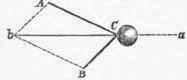
Also, if the force b C were to act in the opposite direction, that is, from a towards C, it would retain the two forces A C and B C in equilibrio; but two forces only can never be in equilibrium unless their directions be exactly opposite, and the forces equal; and the direction they would move in when not exactly opposite, is shown by producing the diagonal of the parallelogram drawn on their directions. Thus C a (Fig. 12) is the diagonal produced, and consequently the direction in which the forces A C and B C would cause the body C to move.
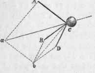
26. If it were required to find the resultant of three forces pressing on the point C, of which the magnitudes and directions were represented by the lines AC, BC, and DC (Fig. 13). In the first place complete the parallelogram B C D b, as in the preceding example; from which we find 6 C to be the resultant of the two forces B C and D C. Then consider b C and A C as two forces, and complete the parallelogram A a b C, and a C is the resultant required; that is, a force, the magnitude and direction of which is represented by a C, would produce the same effect in moving the point C as the three forces A C, B C, and D C. Also, a force equal to a C, and opposite, would keep these three forces in equilibrio.
By pursuing the same method of reduction, the resultant of any number of forces tending to one point may be found; but the same thing may be effected more simply as follows: -
Fig. 13.
27. Let A C, B C, and D C (Fig. 14) be the three forces; * beginning at any force, as at B, make B a parallel and equal to the next force D C; and then make a d parallel, and equal to the other force A C; join d C, and it is the resultant of the three forces.
The figure B a d C is called the polygon of forces, and the number of its sides will always be one more than the number of the forces.
Fig. 14.
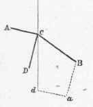
Fig. 15.

28. When any strain is produced by a single force it is sometimes useful to know its effect in a particular direction, in order to apply an equivalent support in that direction. Thus, when a force acts obliquely against the plain surface of an immovable obstacle, the force will have a tendency to slide along the plane; because two forces cannot sustain each other unless they be equal and opposite. Let a force A C (Fig. 15) act upon the even surface of a plane CB; it is evident that only part of this force will be exerted in a direction perpendicular to the plane, and this part will be represented by the line AB, drawn perpendicular to the plane; and then, CB will represent the force that would prevent its sliding along the plane.
* Where forces are represented in magnitude and direction by lines, the lines only are used for the sake of clearness and conciseness to express the forces.
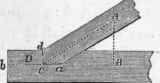
When two pieces of timber are joined obliquely, the pressure on the different parts of the joint may be ascertained by this method; for example, let D B (Fig. 16) represent the end of a tie-beam, and A C the principal rafter; the force in the direction of the rafter being represented by A C. Then A B being perpendicular to the part C a of the joint, will represent the pressure upon it, and the pressure on the part C d will be represented by C B; consequently C B will be the measure of the force tending to splinter off the part D. (See Sect, on ' Joints.')
We cannot often oppose a force by one directly opposite, but we can generally find two forces that will answer the purpose; and by describing a triangle on their directions, and that of the force to be supported, their proportions can always be ascertained. This principle is most important in the theory of carpentry.
29. In general the designs for framing may be so contrived, that the load rests upon two or more points; for example, the weight of a roof acts on the truss which supports it, only at the points where the purlins bear upon the truss; and when these points are supported by struts, the forces may be considered, without material error, to be in the direction of the principal rafters. But when the load is uniformly distributed over the rafter, and it is supported at the ends only, the strain upon the tie-beam is no longer in the direction of the rafter: and as there are some important strains produced by the action of uniform loads, the nature of these strains will form the next object of inquiry.
In order to render the inquiry more clear and simple, let the load be supposed to arise from the weight of the beams themselves.
Fig. 16.
Continue to:
My Books

