Of the Forms of Roofs for different Spans
Description
This section is from the book "Elementary Principles Carpentry", by Thomas Tredgold. Also available from Amazon: Elementary Principles Of Carpentry.
Of the Forms of Roofs for different Spans
228. The simplest form of roof is that shown in Fig. 75, which is adapted for spans under 20 feet.
It consists of common rafters only, which meet against a ridge-piece at the top, and are held together by a horizontal tie, termed a collar-beam. Additional height is given to the rooms by this form of roof, as the ceiling can be formed by nailing boards or lathing to the under-side of the rafters and collars. The scantling of the rafters can be obtained from Table No. 15 at the end of the volume, the whole length be-
* Hatfield's' American House Carpenter,' and 'Instructions for taking Meteorological Observations,' Ord. Survey Departmenttween the supports being taken for the bearing. The collars should be of the same scantling as ceiling joists of the same length of bearing, and they should be slightly notched to fit the rafter.
Fig. 75

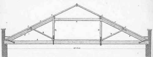
229. For spans of 20 feet and upwards a truss should be used. The form shown in Plate I., which is called a kingpost truss, is adapted for spans of from 20 to 30 feet; within these limits the points of support of the tie-beam and rafters are not too far apart. The scantlings of the timbers are given in Table No. 5 at the end of the volume, according to the span of the roof. The drawing shows a parapet on one side and eaves on the other.
Plate I.
ROOFS.

ROOFS.
230. The form shown in Plate II., which is called a queen-post trust, is adapted for spans exceeding 30 feet and under 45 feet. Each purlin is supported without inducing cross strains on the principal rafters, and the tie-beam is divided into three comparatively short bearings. The scantlings may be obtained from Table No. 6 at the end of the volume.
The sagging which usually takes place from the shrinking of the heads of the queen posts may be avoided by letting the end of the principal rafter abut against the end of the straining beam S; and notching pieces and bolting them together in pairs at each joint. The side marked D of the figure is supposed to be done in this manner. This method is further illustrated in Art. 254, and is applicable to other forms of roof.
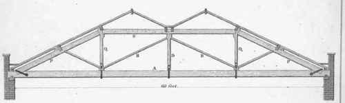
231. "When the span exceeds 45 feet, and is not more than 60 feet, the form of queen-post truss shown in Plate III. is sufficiently strong, and leaves a considerable space in the middle free. For this span the tie-beam will probably require to be scarfed, and as the bearing of that portion of the tie-beam between a and b is short, the scarf should be made there. The middle part of the tie-beam may bo made stronger by bolting the straining sill s to it. The scantlings may bo obtained from the Table No. 7 at the end of the volume; and the methods of scarfing and forming joints are detailed in a separate section.
Plate III.
ROOFS.
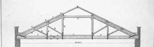
Plate IV
ROOFS.

232. A truss for a roof from 75 to 90 feet span is shown in Plate IV. In this truss the straining sill s should be tabled or keyed, and bolted to the tie-beam in the manner that has already been proposed for increasing the depth of girders (Sect. III.). This truss nearly resembles the roof of the Birmingham Theatre described by Nicholson.*
233. By omitting, or rather reducing, the upper part of the truss in Plate IV. to the same form as that in Plate III., the truss would answer for a bearing of from 60 to 75 feet. The scantlings may be had from the Table No. 8 at the end of the volume.
When the span is so very wide, unless the building be of a proportional height, this form of roof exhibits such an immense amount of plain surface, that the architectural effect of the building is destroyed; besides, it is difficult to light the large space in the roof in any way that would not be open to objection, on account of the external appearance.
234. To avoid a large expanse of roof, the truss may be of the form shown in Plate V., which has been taken from Price's ' British Carpenter.' A roof of this form is called an M roof, and would do for a span of from 55 to 65 feet; but it would be better to adopt the truss represented in Plate IV., making the top flat, and covering it with lead, as the space gained in the roof would amply repay the expense of the lead flat. The scantlings of the M roof may be obtained from the Table No. 9 at the end of the volume.
Plate V.
ROOFS.
* 'Carpenter's Assistant,' p. 61, Plate lxxiii., 2nd edit.
Continue to:
My Books

