Chapter XVI. An Electro-Magnet Traveling Crane
Description
This section is from the book "Carpentry And Mechanics For Boys", by A. Neely Hall. Also available from Amazon: Carpentry and Mechanics for Boys.
Chapter XVI. An Electro-Magnet Traveling Crane

' An electro-magnet is one of the most interesting of the simpler, easily constructed pieces of electrical apparatus which a boy can make. In the author's book The Handy Boy, are shown several things to make with electro-magnets. In this chapter an electro-magnet is shown incorporated in a toy traveling crane (Fig. 394) The crane travels back and forth upon a track supported on chair backs, and the electro-magnet, raised by a cord cable that winds upon a spool drum, will lift as many as two hundred and fifty brads at a time. One of the author's readers who built an electro-magnet derrick like the one described in The Handy Boy, writes that by making a trifle longer electromagnet than that shown in the model, he was enabled to lift a weight of 1 pound 2 ounces. The traveling crane is easy to make.
The Crane Carriage (Fig. 395) is a simple frame built up of two pairs of wooden strips (A and B), mounted upon a pair of ribbon spool wheels (C), with a third spool (D) mounted between for the cable winding-drum, Bore three 34-inch holes through strips A (Fig. 396) for the spool axles. Cut the axles to fit snugly in the holes of the spool wheels and winding-drum (Figs. 397 and 398), and cut their ends to fit loosely in the holes in strips A. Crank F (Fig. 399) is to be fastened to axle E. A similar crank must be fastened to one end of one of the wheel axles (Fig.
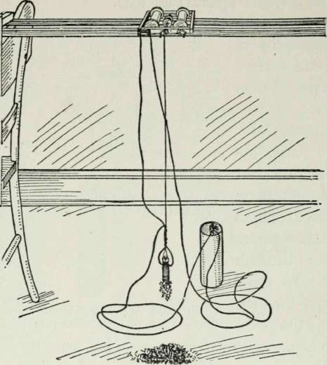
Fig. 394. - The Electro-Magnet Traveling-Crane
395). A long brad forms the crank-handle. The handle for the winding-drum crank should fit loosely, and several small holes should be drilled in stick A in the correct positions so the crank handle can be pushed into them to lock the winding-drum at any point desired (Fig. 395). The crank on the wheel axle moves the crane carriage along its tracks.
Make the Tracks of Sticks heavy enough to support the carriage and loads to be hoisted, without bending. Nail strips across the ends of the track sticks to hold them at the proper distance apart (Fig. 394).
The Electro-Magnet has a core of soft iron encased in a coil of wire. When an electric current passes through this coil, the core becomes a magnet, but it retains its magnetism only as long as the current continues to pass through the wire. In using an electro - magnet, therefore, the electric current must be passed through the coil continuously while a load is being lifted, and shut off when the load is to be dropped.
Figure 400 shows the completed electro-magnet. A carriage-bolt about 2 1/2 inches long and 1/4 inch in diameter is needed for the magnet

Fig. 399 Fig. 396 Fig 397
Figs. 396-399. - Details of Crane Carriage core, insulated electric-bell wire for the coil, cardboard, paper, and a dry-battery cell.
Cut three cardboard washers of the diameter of the bolt-

Fig. 400. - The Electro-Magnet
Fig. 401 and 402. - Detail Showing Magnet Winding head (Fig. 401), slip them over the bolt, and screw on the nut (Fig. 402). Then slip one end of the wire between the upper two washers, and, starting at that end, wind the wire around the bolt, pushing each turn close to the preceding turn. When the head of the bolt is reached, wind back to the starting point; then wind back to the head again, and so on until four or six layers have been wound on. Slip the second end of the wire between the cardboard washers., and screw the nut tight to hold the coil in position. Figures 394 and 395 show how one wire end of the coil
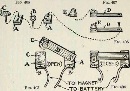
Figs. 403 and 404. - Switch Open and Closed
Fig. 405. - Details of Binding-Post and Contact Plates
Figs. 406-407. - Details of Switch is connected by wire with a dry-battery cell, how the other end is connected with a switch on the crane carriage, and how a third wire connects the battery with the switch.
The Switch for opening and closing the electric circuit is shown in Figs. 403 and 404. Make the contact plates A out of tin or brass (Fig. 405), and punch holes through them for screw-eye binding-posts B, for brass tack contact point C, and for the lever screw. Make lever D (Figs. 406 and 407) of tin or brass, with turned up tips on one end to tack to the wooden knob E.
The Hoisting-Cable cord is to be attached to the top of the magnet, then run up and over the winding-drum spool, and glued to it.
Continue to:
My Books

