Lesson XXI. Making A Paneled Door. - Isometric Drawing
Description
This section is from the book "Manual Training: First Lessons In Wood-Working", by Alfred G. Compton. Also available from Amazon: First Lessons In Wood-Working.
Lesson XXI. Making A Paneled Door. - Isometric Drawing
In Lesson XIII (Back-Saw And Bench-Dog) you planed up the sides of your box and put them away; and when you took them out again you found that they had shrunk in width though not in length, and you measured the amount of the shrinkage. You found also that some of the pieces had checked, and some had warped. When large pieces of wood are used, shrinkage, warping, and checking give rise to serious trouble. Thus, in a door 30 inches wide shrinkage may amount to half an inch or more, and warping to an inch, and long and wide cracks are almost sure to appear. Moreover, the shrinking does not take place once for all, and then come to an end, but the wood having once shrunk may swell again, and shrink again, and so on repeatedly. Doors that are exposed to the dry air of houses which are heated in winter become very loose, but sometimes swell up in summer so much as to stick. The shrinkage will be less if the wood has been thoroughly seasoned, but the swelling in damp weather can hardly be prevented.
Doors are therefore never made in one piece, but are always constructed of parts, so arranged as to reduce as much as possible the bad effects of these changes. There are two principal methods of construction by which this is accomplished. The first is the battened door and the second the paneled door. The battened door is made of strips, Fig. 60, running lengthwise of the door and held together by cross-strips or battens, fastened on with screws or nails. As the wood shrinks only in width and not in length, the shrinking of the strips will only cause the edges to separate a little, and will produce scarcely any change in the width of the door. The warping, also, in this case, will be small in amount. While a piece the whole width of the door might warp, as at a, Fig.

Fig.60.
61, a battened door would appear as at b. The separating of the strips, leaving cracks in the door, is prevented by using "matched" boards, or "tongue and groove" joints, as shown in the plan Fig. 60, or on a larger scale in Fig.
62. In this case the tongues slip partly out of the grooves when the wood shrinks, but do not leave the joints open. This construction is simple and effective, and is much used where fine workmanship and handsome appearance are not important, as in the doors of barns and outhouses. For dwelling-houses and in cabinet-work the paneled door is used. This is a frame-work mortised together at the corners, and grooved all round on the inner edge to receive a thin piececalled the panel,as shown in Fig. 63. The shrinking of the panel only causes it to slip in the groove. As the cross-pieces at the top and bottom undergo no change in length, the only alteration in width that the door will suffer is the slight one due to the shrinking in the width of the two upright pieces. We will proceed to make such a door from the figured sketch, in which A shows the elevation, B the plan, and C a section on the line a b.

Fig. 61.

Fig.62.
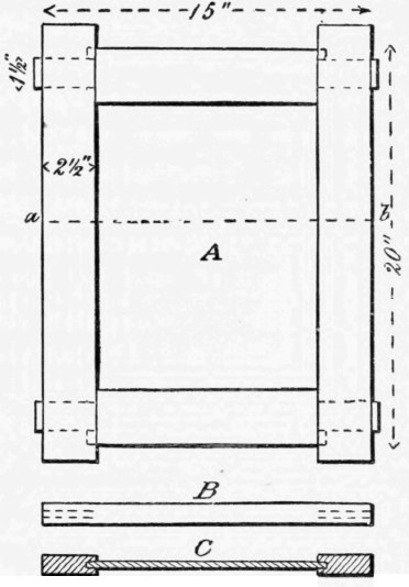
Fig.63.
The first step is to get out the material. This consists of the top and bottom pieces, called the rails, the upright sides, called stiles, and the thin central piece or panel. Take the dimensions of these from the drawing, and mark them out on boards of the proper thickness, being careful to allow for the saw-kerf and for the material which will be wasted in planing up the pieces to the true shape and dimensions. Furthermore, as the mortises will be very near the ends of the stiles, the latter may be cut 1¥' longer than the door, so that they may project 3/4" at each end, as in the Figure, and the tenon-pieces, or rails, may be made 1" longer than the width of the door, so that the tenons may project 1/2" beyond the stiles till all is finished, after which the projecting parts can be cut off. The rails, therefore, will be cut out 16" long and the stiles 21 1/2" long.
In laying out the frame, try, as in Lesson VIII (Making A Nailed Box. Laying Out The Work). to avoid knots and cracks, and at the same time to waste as little wood as possible. The four pieces may be laid out in one way or another, according to the character of the wood from which they are to be cut. If the board were much checked at the end, as in Fig. 64, you should cut off just enough to remove the short cracks, and might then lay out the work so that the long cracks which remain should lie in the waste-wood left at the ends of the short pieces. If there were a bad knot at a, Fig. 65, this might be made to fall in the wastewood between the rails and the stiles; and so on, according to the position and character of the defects.

Fig. 64.

Fig. 65.
The frame-pieces being cut out, they are to be finished to exact dimensions and true surfaces as in previous lessons. The joints are then to be marked out with gauge, square, and pencil, making all gauge and square marks from the front surface and inner edge of the pieces, which must be marked to distinguish them.
The laying out of the joint in this exercise is complicated by two circumstances. The first of these is that the tenon must be made of less width than the full width of the rail, in order that the mortise may not run out quite to the end of the stile. The second is, that a groove is to be cut in the inner edge of the four pieces, and this groove, unless a special arrangement is made to prevent it, will leave a hole between the end of the stile and the shoulder of the mortise, as shown in the sketch of one joint at a, Fig. 66. To prevent this, a projecting stud, or tooth, is left on the tenon-piece, as shown in plan and elevation at a and b, Fig. 67, This construction, and the method of laying it out, may be better understood by the help of another kind of drawing called Isometric Projection, the elements of which can be easily understood.
The elevations and plans that we have hitherto used are projections on planes parallel to the front, bottom, and sides of the object; that is to say, they are views taken from a point at a great distance in front of the Object, above it, or to one side of it. The eye being at a very great distance from the object, if a plane be placed parallel to the face of the object, the lines drawn from all points of the object to the eye are perpendicular to the plane. If lines are thus drawn from all points on the edges and other lines of the object, they cut the plane in a number of lines which make up what is called the projection of the object. The elevations and plan already drawn are such projections, and are called right projections. If we take our point of view not exactly in front of the object, but a little to one side, or if, which is the same thing, we turn the object so that its front is not parallel to the plane of projection, the appearance of the object is changed, and the projection is called an oblique projection. The front of the object appears narrower, and the side, which was invisible before, comes into view. Suppose, for instance, the object were a cube, of which the plan is A, Fig. 68. Then, on the plane of projection, the front of it appears as a square, in the elevation B, and the side a is not seen at all in this elevation. But, if the cube be turned round to the position C, Fig. 69, the front face will appear narrowed, or "foreshortened" to the width bc, and the right-hand face will come into view and will have the apparent breadth c d, The elevation, therefore, will now present the appearance shown in 7), Fig. 69, where b c f g represents one of the visible faces of the cube, c d h f another, and e d h i and b e i g the two invisible or rear faces. If we take the point of view still farther to the right, or turn the object farther round, the front becomes apparently narrower, the right face wider, and the two appear presently of equal width.
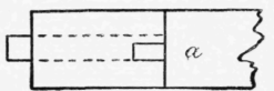
Fig. 66.
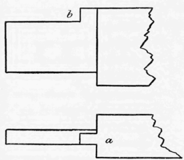
Fig. 67.

Fig.68.

Fig. 69.
This happens when the square C, Fig. 69, has been turned so that its diagonal is perpendicular to the plane of projection, as at E, Fig.
70. The elevation then appears as at F, in which a b and c d represent the faces of the cube, and appear of equal width. If, now, we take our point of view not only to the right of the object, but also higher, the vertical lines will be foreshortened also, the upper surface willcome into view, and the cube will appear as in Fig.
71. If the point of view be taken still higher, the edge P Q will be made to appear of the same length as P R and P S, Fig. 72. All dimensions which are parallel to either edge are then equally foreshortened, and the drawing is called an isometric drawing or isometric projection. The dotted lines in Fig. 72 show the edges of the cube that are concealed. The drawing of a cube on this system is thus seen to be extremely simple: that of a body with unequal dimensions is not difficult, provided its faces are perpendicular to each other. Thus, if it is required to represent a body of this shape whose length, breadth, and thickness are respectively 3", 2", and 1", we have only to draw three lines P Q, P R, and P S, Fig. 73, making equal angles with each other, and to lay off on -the one three units of length, on the second two equal units, and on the third one of the same units, and complete the drawing as in the figure. The drawing of the three lines, or "axes" P Q, P R, and P S is easily accomplished, as in Fig. 74.

Fig. 70.

Fig. 71.
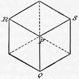
Fig. 72.

Fig. 73.
Draw a circle with any radius. From the highest point on the circumference lay off the radius six times, and through the alternate points draw the three axes. To secure accuracy the radius should be taken at least as long as the longest line in the drawing.
It will be well, now, to make a few isometric drawings of simple objects, such as the box of Lesson XX (Fitting Hinges)., the through mortise of Lesson XV (The Chisel Continued), and the end dove-tail of Lesson XVI (The Chisel Continued. - End Dove-Tail)., to accustom the eye to the "reading" of such drawings. It will be readily seen by those who understand ordinary perspective drawings, that isometric drawings differ from these only in giving the true dimensions of the remote as well as of those of the near parts, while perspective drawings make the parts that are farther away appear smaller, and therefore a scale cannot be applied to them.

Fig.74.
Continue to:
My Books

