Halving
Description
This section is from the book "Workshop Notes & Sketches For Handicraft Classes", by Thomas A. Clark. Also available from Amazon: Workshop notes & sketches for handicraft classes.
Halving
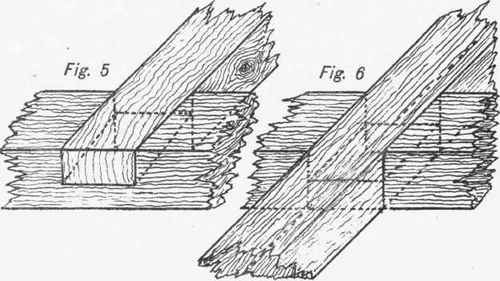
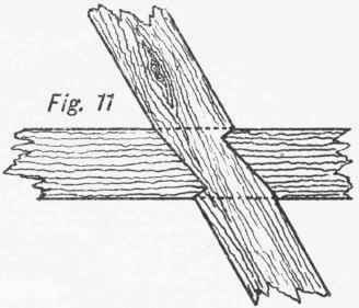
This class of joint is used for a great many different purposes, and the joint itself assumes quite a number of forms, depending upon the application. Halving is much applied in housebuilding, as also in many pieces of general framing used in mechanical engineering, etc. Applications of this joint are very common, as a casual observation will show. Figs, 1 and 2 are selected when the ends cannot be allowed to pass beyond the flush of the sides, Figs. 3, 4, and 5 when one end may pass, but the other be flush or even with the side, and Fig. 6 when both ends may project. Figs. 2 and 4 are called dovetail halving and Fig. 5 bevelled halving. These joints may be used for uniting pieces either at right angles or obliquely as Figs. 7, 8, and 9. Figs. 10 and 11 are applications of the same joint, but many additional ones are in common use.


In making halving joints, or in fact any class of joint, one of the chief points of the work is to have the several parts properly proportioned, and the lines carefully drawn on. As the same general instructions are suitable for all these joints, a description of one, say Fig. 4, will suffice for the whole. Fig. 4 is known as dovetail halving, because of the shape of one part of the joint, after the side pieces have been taken off. The first thing to be done, after the wood is planed to required sizes, will be to arrange the pieces for jointing, so as to have the edges to the most suitable sides, and the faces to the top or same side. In this instance, shown in detail at Fig. 12, the edge of a may be kept inside, while that of b may be put to right or left. The reasons for placing or arranging pieces in a certain way before jointing, are, that certain surfaces may be to certain sides when the work is completed, and that every advantage may be taken of the true surfaces, to secure good and close joints. The faces are kept to the same side, so that if any gauging has to be done, the surfaces will be flush when the pieces are put together, as half is taken out of each; and likewise to have all the best surfaces to one side. In some joints it is best to make one part first, and then make a transfer by the use of a sharp pencil, a marker, or chisel edge. This, however, is only advisable when it would take longer time by measurement, or be likely to prove less correct when done. As one of the chief aims of this sort of education is to obtain accuracy of observation, all methods likely to beget the opposite should be avoided. To this end, careful measurement should be insisted on at a very early stage, and no guess work encouraged, or allowed to pass. It is one of the worst possible styles of doing work, to allow so much for fitting, and then gradually take it off piece by piece until the proper size is arrived at. This must be done in some instances, but should by no means be recognised as the right way, if it is practicable to measure the sizes exactly.
The first line to be drawn is C d across the under side of b (Fig. 12), square to its edge and about 1/16 in. further from the end than the width across a. Lines c e and d f are to be drawn square across the edges from the ends of this line, and care should be taken in every squaring operation to have the brass edge of the square stock firmly placed against either face or edge. The last line drawn square across the face, if correct, should exactly join the ends, e and f, of the two lines on the edges. The lines for the sides of the dovetail may then be put on, allowing sufficient taper to give strength, while keeping the neck of suitable width. Equal distances e g and f h are to be measured along the line e f and the points g and h joined to the points 1 and j at the extreme corners. Although not absolutely necessary, the same may be done on the opposite side, in order to have an additional safeguard and guide. This may be of no service, as the under piece of b, on which the extra lines would be drawn, may be cut off before the other process is performed. If found necessary these lines can be put on after the slab has been removed, but as the square may be readily applied from the face, these extra lines will be found of less importance. Corresponding lines G' i' and h' j' can now be put upon the face of a, and the ends of the two lines squared half down the edges. The marking gauge should then be set to half the thickness of the wood, and gauge lines drawn off the faces, along both edges of each piece and on the end of b. Both pieces are now ready for the making of the joint. As it is somewhat difficult to begin the saw-cuts accurately by the lines, and seeing that the saw does not leave a very smooth edge, it is better in the first place to form a small shoulder or angular groove, with the paring chisel, to insure an exact beginning. To do this, place the square close by the line, holding tightly with the left hand, while the chisel is held in the right in an upright position, to form a square edge, and with its flat side against the square blade, but tilted so as to make the corner cut easily. A light line is first drawn across, and if correct, thereafter made of suitable depth, say 1/16 in. The chisel is then sloped over to the angle of about 450, and inserted so as to reach down to the bottom of the vertical cut already made. If this groove be well formed, the tenon saw may be entered without difficulty. The piece of wood b - inverted - is shown with these grooves formed at b', Fig 12. The same may be done across both edges of b, and also across by the oblique lines on the face of a. It will be found advantageous to resort to this process wherever a shoulder is to be made, or in fact, when any surfaces of this kind are to be fitted together, and on which the planes cannot be applied. The nature of each joint must be studied, for it may be easily spoilt by taking out the sloping surface with the chisel at the wrong side of the lines, and instead of a close joint the reverse will be the result. The tenon or dovetail saw would now be brought into requisition, and the several parts cut, while the slab, below the gauge lines on b, would be cut off, or in the case of small pieces with straight grain, they might be split with the paring chisel. Sawing will be found to be generally the better and quicker method. The bench-hook and vice will each be found suitable for holding the work during certain cuts - the former when the wood is horizontal and the latter when vertical. As the saw leaves a good enough surface for the inside of the joint, it should be the endeavour of the workman to saw so exactly as to require little or no paring down to the lines, and thus much time will be saved. The side pieces, to form the dovetail, would be taken off in a similar manner. The piece above the gauge lines on a can be split out with the chisel and then pared to the lines. Before driving the pieces together, a slight chamfer should be taken off the under corners of the dovetail, to make it enter more easily. This joint may be fixed together by glue, pins, nails, or screws. As already remarked, those joints are so much alike in point of construction that it is quite unnecessary to give a detailed description of each - all that has to be attended to, is to make sure of the sort of joint best suited for the work, and to have the parts properly proportioned and well fitted.
Continue to:
My Books

