History Of The Lathe. Introduction Of Screw Threads. Part 4
Description
This section is from the book "Lathe Design, Construction And Operation, With Practical Examples Of The Lathe Work", by Oscar E. Perrigo. Also available from Amazon: Lathe Design: Construction And Operation.
History Of The Lathe. Introduction Of Screw Threads. Part 4
The large wheel was of cast iron, rescued from a scrap heap, and had only the grooves for the two faster speeds K, L, the part M being made of wood and fastened to the arms of the wheel. A friendly blacksmith forged the cranks in the shaft N, and the eyes in the lower ends and hooks in the upper ends of the connecting rods P, P. These were first made of wood similar to the connecting rods on a sewing-machine with a closed bearing at the top, but the tendency to pinch one's toes under the treadle when they happened to be accidentally placed in this dangerous position soon led to the iron connecting rods with the hooked ends whereby the worst that could happen was the connecting rods becoming unhooked. The shaft N rested in wooden boxes, the lower half being formed in the cross-bars C, C, and a wooden cap held down by two wood screws forming the top half. The bearings of the shaft and the cranks were filed as nearly round as they could be made by hand with the means and ability available.
The pattern for the head-stock was made as shown in side elevation in Fig. 5, with the housings for the spindle boxes as shown in Fig. 6. The boxes were made in halves, of babbitt metal and cast in place in the head-stock in this manner. The head spindle was located in place and held by a thin piece of wood clamped on the inside and outside of the housing and having semicircular notches in their upper edges and a slight recess on their inner sides so as to provide for making the box slightly thicker than the housing.
The lower halves of the boxes, having been cast slightly higher than the center of the spindle bearings, were removed and filed down to the proper level and then replaced, the spindle again laid in, the strips of wood clamped on in an inverted position and the top half of the box cast. This part projected slightly above the top of the iron casting and was held down by an iron cap having two holes drilled in it which fitted on the threaded studs R, R, which had been cast into the head-stock for this purpose. The spindle had been turned up in an old-style chain-feed lathe, of which more will be said later on. The cone pulley S was of cherry, simply driven on tightly and turned up to the form shown.
The front end of the spindles was threaded but not bored out. Upon this thread was cast a babbitt metal bushing T, having a square hole in its front end, which was formed as follows: With the spindle in its place a wooden mold of proper form was placed around it and, while it fitted the collar on the spindle at one end, was open at its front end. A tapering, square piece of iron of proper dimensions to form the square hole was placed with its small end against the nose of the spindle and held in that position by the tail screw. The opening around it was closed by a piece of wood of proper form and the job was "poured," and the bushing afterwards turned up with a hand tool. Into this square hole could be fitted proper centers for turning wood or metal, and by removing the babbitt metal collar a face-plate could be put on for face-plate work.
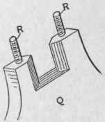
Fig. 6. - Spindle-Box Housings.
It will be noticed that the lathe had been arranged for two speeds proper for turning wood and the softer metals, and one speed considerably slower for iron. A piece of belting was provided which could be easily removed to shorten the belt the proper amount for this purpose.
The lathe would swing eight inches and take in between centers four feet. It was found that the round belt did not give sufficient driving power and a new spindle cone of only two steps was put on, the iron balance-wheel lagged up for a flat belt, and the pulley M turned down for the same purpose. This permitted the use of a belt an inch and three-quarters wide, and as no regular belting was available when the job was done an old trace from a harness suffering from general debility was ripped open and a single thickness of the leather soaked up in water, dried out, treated with neat's-foot oil and used with such good results that it was never replaced.
To this lathe was fitted a small circular saw provided with an adjustable, tilting table upon which not only wood but sheet brass could be cut. Another attachment was a small jig-saw that would cut off wood up to half an inch thick.
One of the disadvantages of the usual form of foot-power lathe was the short connecting rod or pitman which thereby formed too great an angle to the center line from the wheel center to the point of attachment to the treadle, thereby increasing the friction and decreasing the useful effect of the foot-power. It was apparently to avoid this condition that a somewhat peculiar form of lathe was devised and built in the railroad shops at Plattsburgh, N. Y., about 1860, and which is shown in end elevation in Fig. 7. This was an engine lathe of about fourteen-inch swing, built with cast iron bed A, legs B, and all the parts of metal that are now so constructed. Instead of placing the large driving or balance wheel beneath the lathe bed as formerly, the lathe was belted from a cone pulley of three steps on an overhead countershaft C, provided with the usual hangers D. This countershaft was of a length equal to the length of the lathe and had fixed at the end over the head of the lathe a heavy wheel E, into the hub of which was fixed a stud or wrist-pin F, while on the opposite end of the countershaft was fixed a disc for carrying a similar stud. These formed two cranks to which were fitted long connecting rods G, the lower ends of which were pivoted to the treadles H, whose rear ends were pivoted to the legs B, as at J. The treadles H are located outside of the legs B, and connected by the foot-board K. The weight of the connecting rods G, the treadles H, and the foot-board K are balanced by the proper counterbalance added to the fly-wheel E, as shown. The author knows from personal observation that this lathe would run very steadily and with a good deal of power, and that its general performance was much better than foot lathes of the usual type. Doubtless the momentum of the balance-wheel, cone pulley, and countershaft was very beneficial in maintaining an equable speed under varying conditions of resistance from the operation of cutting-tools and the like, while the cast iron cone pulley on the main spindle did some service in the same direction.
The only disadvantage in this lathe was that it required too long a time to get it up to its regular speed and necessarily too much time was consumed in stopping it, as there was no provision for disconnecting the main spindle from the driving-cone by a clutch mechanism or similar device, as is frequently the case with special forms of the lathes of recent design.
There has been manufactured for some years a special type of friction clutch that is very useful in driving foot-power machinery. It consists essentially of a drum mounted upon and loosely revolving around the shaft to be driven, and having a friction, clutch mechanism contained within it and so operating that the drum will turn freely in one direction but the moment it is revolved in the opposite direction the friction device comes into operation, the drum is firmly clamped to the shaft, which is thus caused to rotate with it. To this drum is attached one end of a flat leather belt, which is wrapped around it several times and its free end attached to the movable end of a treadle, which is usually hinged at the front instead of the back of the machine. In operation the pressure of the foot acting on the drum by means of the belt rotates it in the forward direction, which causes its friction mechanism to act and revolve the shaft through as many revolutions as there are convolutions of the flat belt around the drum. The rotary motion thus set up is continued by the momentum of a balance-wheel, and as the foot is raised the treadle is caused to follow it, either by the action of a spring similar to a clock spring within the revolving drum, or a spiral spring acting upon another strap, also wrapped around the drum, but in the opposite direction to the one attached to the treadle. By this device several revolutions of the driving-shaft could be produced at each depression of the foot, the treadle frequently passing through an arc of thirty to forty degrees.

Fig. 7. - Foot Lathe, Driven from a Countershaft.
This device was particularly applicable to the driving of light foot-power machinery which it did very successfully, and as the strokes of the foot need not be of the same length and were not confined to any certain cadence it was not nearly as fatiguing as the crank device in which the strokes of the foot were always the same distance and with the same speed.
In the above described device, however, the balance-wheel was more necessary and it was also necessary that it should be so arranged as to revolve with a much higher rate of speed than the large wheel of the older form of foot lathe. There was one advantage in this condition, however, that in consequence of its higher speed the balance-wheel could be made of much smaller diameter and consequently much lighter in weight, and therefore occupying much less space under the machine.
Continue to:
My Books

