Cleavage Test
Description
This section is from the book "The Mechanical Properties Of Wood", by Samuel J. Record. Also available from Amazon: The Mechanical Properties Of Wood.
Cleavage Test
A static testing machine and a special cleavage testing device are required. (See Fig. 44.) The latter consists essentially of two hooks, one of which is suspended from the centre of the top of the cage, the other extended above the movable head.
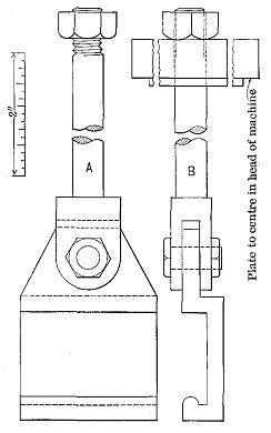
Figure 44
Design of tool for cleavage test.
The specimens are 2" × 2" × 3.75". At one end a one-inch hole is bored, with its centre equidistant from the two sides and 0.25 inch from the end. (See Fig. 45.) This makes the cross section to be tested 2" × 3". Some of the blocks are cut radially and some tangentially, as indicated in the figure.
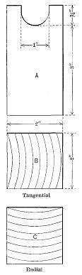
Figure 45
Design of cleavage test specimen.
The free ends of the hooks are fitted into the notch in the end of the specimen. The movable head of the machine is then made to descend at the rate of 0.25 inch per minute, pulling apart the hooks and splitting the block. The maximum load only is taken and the result expressed in pounds per square inch of width. A piece one-half inch thick is split off parallel to the failure and used for moisture determination.
Continue to:
My Books

