Impact Test
Description
This section is from the book "The Mechanical Properties Of Wood", by Samuel J. Record. Also available from Amazon: The Mechanical Properties Of Wood.
Impact Test
Apparatus: There are several types of impact testing machines.59 One of the simplest and most efficient for use with wood is illustrated in Figure 40. The base of the machine is 7 feet long, 2.5 feet wide at the centre, and weighs 3,500 pounds. Two upright columns, each 8 feet long, act as guides for the striking head. At the top of the column is the hoisting mechanism for raising or lowering the striking weights. The power for operating the machine is furnished by a motor set on the top. The hoisting-mechanism is all controlled by a single operating lever, shown on the side of the column, whereby the striking weight may be raised, lowered, or stopped at the will of the operator. There is an automatic safety device for stopping the machine when the weight reaches the top.
[Footnote 59: For description of U.S. Forest Service automatic and autographic impact testing machine, see Proc. Am. Soc. for Testing Materials, Vol. VIII, 1908, pp. 538-540.]
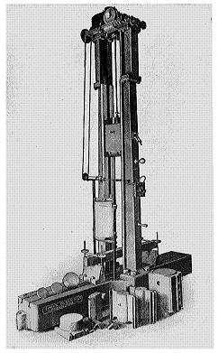
Figure 40
Impact testing machine.
The weight is lifted by a chain, one end of which passes over a sprocket wheel in the hoisting mechanism. On the lower end of the chain is hung an electro-magnet of sufficient magnetic strength to support the heaviest striking weights. When it is desired to drop the striking weight the electric current is broken and reversed by means of an automatic switch and current breaker. The height of drop may be regulated by setting at the desired height on one of the columns a tripping pin which throws the switch on the magnet and so breaks and reverses the current.
There are four striking weights, weighing respectively 50, 100, 250, and 500 pounds, any one of which may be used, depending upon the desired energy of blow. When used for compression tests a flat steel head six inches in diameter is screwed into the lower end of the weight. For transverse tests, a well-rounded knife edge is screwed into the weight in place of the flat head. Knife edges for supporting the ends of the specimen to be tested, are securely bolted to the base of the machine.
The record of the behavior of the specimen at time of impact is traced upon a revolving drum by a pencil fixed in the striking head. (See Fig. 41.) When a drop is made the pencil comes in contact with the drum and is held in place by a spring. The drum is revolved very slowly, either automatically or by hand. The speed of the drum can be recorded by a pencil in the end of a tuning fork which gives a known number of vibrations per second.
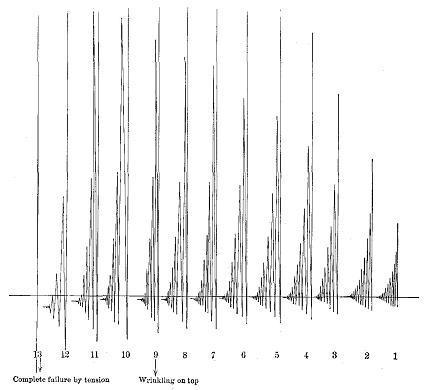
Figure 41
Drum record of impact bending test.
One size of this machine will handle specimens for transverse tests 9 inches wide and 6-foot span; the other, 12 inches wide and 8-foot span. For compression tests a free fall of about 6.5 feet may be obtained. For transverse tests the fall is a little less, depending upon the size of the specimen.
The machine is calibrated by dropping the hammer upon a copper cylinder. The axial compression of the plug is noted. The energy used in static tests to produce this axial compression under stress in a like piece of metal is determined. The external energy of the blow (i.e., the weight of the hammer × the height of drop) is compared with the energy used in static tests at equal amounts of compression. For instance:
| Energy delivered, impact test | 35,000 inch-pounds | |
| Energy computed from static test | 26,400 inch-pounds | |
| Efficiency of blow of hammer | 75.3 per cent. |
Preparing the material: The material used in making impact tests is of the same size and prepared in the same way as for static bending and compression tests. Bending in impact tests is more commonly used than compression, and small beams with 28-inch span are usually employed.
Method: In making an impact bending test the hammer is allowed to rest upon the specimen and a zero or datum line is drawn. The hammer is then dropped from increasing heights and drum records taken until first failure. The first drop is one inch and the increase is by increments of one inch until a height of ten inches is reached, after which increments of two inches are used until complete failure occurs or 6-inch deflection is secured.
The 50-pound hammer is used when with drops up to 68 inches it is reasonably certain it will produce complete failure or 6-inch deflection in the case of all specimens of a species; for all other species a 100-pound hammer is used.
Results: The tracing on the drum (see Fig. 41) represents the actual deflection of the stick and the subsequent rebounds for each drop. The distance from the lowest point in each case to the datum line is measured and its square in tenths of a square inch entered as an abscissa on cross-section paper, with the height of drop in inches as the ordinate. The elastic limit is that point on the diagram where the square of the deflection begins to increase more rapidly than the height of drop. The difference between the datum line and the final resting point after each drop represents the set the material has received.
The formulæ used in calculating the results of impact tests in bending when the load is applied at the centre up to the elastic limit are as follows:
| 3 W H l | |||
| (1) | r | = | ----------- |
| D b h2 | |||
| F S l2 | |||
| (2) | E | = | ----------- |
| 6 D h | |||
| W H | |||
| (3) | S | = | ------- |
| l b h | |||
| H | = | height of drop of hammer, including deflection, inches. | |
| S | = | modulus of elastic resilience, inch-pounds per cubic inch. | |
| W | = | weight of hammer, pounds. |
Remainder of legend as on page 98.
Continue to:
My Books

