A Combined Scroll Saw, Tool Grinder, Router, And Drill Press
Description
This section is from the book "Handy Man's Workshop And Laboratory", by A. Russell Bond. Also available from Amazon: Handy Man's Workshop And Laboratory.
A Combined Scroll Saw, Tool Grinder, Router, And Drill Press
Perhaps many an amateur is looking around for something to turn his lathe or to drive his emery wheel, or may be he is thinking of making a jig saw that will compare favorably with the best; not a mere toy, but a saw of practical value; a saw that one man can operate, and that is capable of cutting through a 2-inch oak plank if necessary. Of course the amateur will take more pride and pleasure in a machine made by his own hands, and will strive to have it much hotter in many respects than anything on the market.

Fig. 45 - Combined scroll saw, tool grinder, router and drill press.
The accompanying illustrations are intended to show just how a practical machine of the kind can be built, and it will enable him to bring into active service, again, the old and forgotten bicycle he stored away in the attic some years ago. No attempt has been made to show any details of the driving mechanism, as of course that will largely depend upon the gear and make of the bicycle to be used, and on such old gearwheels and pinions as the amateur may have on hand, or is able to purchase. Almost anything will do, as long as the proper speed of the saw is obtained, which should be six to seven strokes to one revolution of the pedals. The arms with their fastenings are detailed very carefully, and if the dimensions are closely adhered to there will be no trouble in assembling them. The mountings as well as the saw blades, in different widths, may be bought in the market.
Fig. 45 represents a side elevation of the scroll saw with its accessories, which consist of a tool grinder A, molder B, and drill press C. A .grater mill, such as used for grinding apples for cider and the like, may be added as shown in dotted lines.
The Scroll Saw
A table, supported on suitable legs, shown in Fig. 46, is made first. To this the bicycle is securely fastened at the front and rear ends. The rear hub is secured on one side to an ordinary shelf bracket 1, depending from the table, and on the other to a small brace 2. which is better shown in the plan view. Fig. 47. The front forks, 3, are cut off and with front hub 4 are fastened to a block of wood, 5, depending from the under side of the table. This block also forms a support for the crankshaft, 6.

Fig. 46 - The scroll-saw table.
It will be noticed that the rims as well as the spokes of the wheels are removed, also the steering post is taken out and the saddle is turned end for end. To the flange of the rear hub, 7. is bolted a large gear wheel, 8, meshing with a pinion, 9, on the front hub, 4. which also carries another large gear. 10. meshing into another gear, 11. fastened to crankshaft. 6. The latter gear carries a wrist pin, 12. and is connected to the lower arm, 13, of the saw frame by means of a pitman. 14. One of the flanges of the front hub, 4, is cut off, and the gears 9 and 10 are slipped on and soldered fast to the barrel of the hub. The gear train from the sprocket chain to the saw frame is shown in Fig. 48. At the opposite end of crankshaft 6 is fastened a small flywheel, 15, with a handle, 16; its purpose to be explained later. It is now evident that when the operator works the pedals the crankshaft 18 will revolve and the saw-carrying arms, 13 and 13a. owing to their connection therewith will be moved up and down. The arms 13 and 13a are made of hard wood, such as maple or hickory. They are fulcrumed at the rear end of the table and are provided with suitable fastenings at their forward ends to receive the saw blade, while their rear ends are connected by a suitable turnbuckle to regulate the tension of the saw blade. To the arms are bolted small brackets, 21 (see Fig. 49), made of sheet steel about 1/8 inch thick, which have at their outer ends small half-round recesses, 22, made by a very blunt chisel on top of a piece of hard endwood.
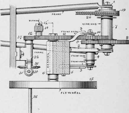
Fig. 47 - Plan view of the gearing.
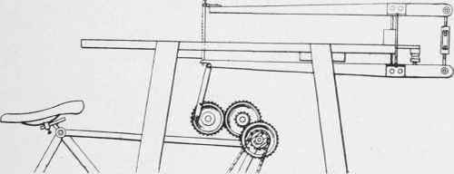
Fig. 48 - Gear train from sprocket chain to saw frame.
To the rear end of the table is fastened a short block of wood, 23, say 8 inches long, and on this block is fastened a small steel plate, 24, with projecting ends, 25, which fit into the recesses, 22, of the brackets, 21, on which the arms 13 and 13a rock. In close proximity to this plate is an iron rod passing through said arms riveted at each end, with a leather washer between, which serves as a cushion and allows sufficient flexibility to enable the arms to swing on their fulcrum. The clamping devices for the saw are made of wrought iron or steel. The lower clam]) has downwardly extending lugs for connection with the pitman. It will be noticed there is a small recess at the top and bottom to receive a cross pin or nail, which passes through the saw Made and serves to keep the blade from slipping through the clamp. The lower bracket is securely bolted to the arm, whereas the upper one is adjustable forward or rearward, according to the width of the saw blade used. The pitman is made of hard wood.

Fig. 49 - The saw frame fulcrum and connections.
A small pneumatic or bellows is secured to the table, and is operated by the movement of the lower arm 13. It is connected with a small rubber hose terminating in close proximity to the saw blade so that the sawdust will be blown away from the line or mark which the cut is to follow.
Now for ordinary work the operator is seated on the saddle, and treads the pedals, having his hands free to manipulate the work, but in case the work should be so large that the operator could not use the saddle, he may stand at one side of the machine and operate the saw with the hand by using the handle 16 on the flywheel, while with the other hand he can guide the work under the saw. A suitable guide may be attached to the table for straight work.
Tool Grinder
The tool grinder consists of an old bicycle hub, 26 ( Fig. 50), to which is soldered a suitable leg or support, 27, made of say 1 1/2 x 1/8- inch iron, which is fastened to a hinged block, 28, with wood screws. To the central rod of the bearing is fastened a small pulley on one side, and an emery wheel on the other. The block is hinged to the main table, and held in upright position with a sliding bolt 29, which is pushed under the block, when the emery wheel is in use.
When the wheel is not in use the bolt 29 is withdrawn, allowing grinder to swing downward, as indicated by dotted lines in Fig. 50. In this position it will not interfere with the free movement of the work on top of the table. The emery wheel is driven by a small belt from the flywheel 15. The wheel should run about 1,000 revolutions per minute, but of course that is governed by the rate of pedaling.
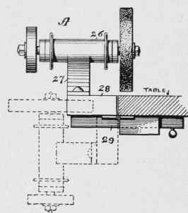
Fig. 50 - Hinged mounting of the tool grinder.
Drill-Press
Fig. 45 shows in dotted lines a portion of a small drill-press clamped to a rail, fastened to the under side of the table, and driven by a belt from the flywheel 15. The tool is shown to better advantage in Fig. 51. This makes a very handy and a convenient way to operate the drill. The drill-presses on the market generally have an arrangement for changing the speed. and almost any speed on the drill may be obtained.
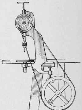
Fig. 51 - The drill-press.
Router
The router or molder consists of a small cutter head. 30 (Fig. 52), fastened with a set-screw to shaft 31, mounted in suitable bearings 32 and 33. To the lower end of the shaft is fastened a small bevel gear, 34, meshing with another, 35, mounted on a shaft, 36. The latter revolves in a bracket, 32 (see Fig. 47 ). At the opposite end of the shaft 36 is a small pinion, 37, meshing with the gear wheel 11. The bracket 32 is made to slide up and down a short rail. 38, fastened to the legs of the table, and it may be held in position by a bolt, 39. Fig. 52 shows the train of gears in mesh and ready for operation. By unscrewing the nut of said bolt, the bracket may be moved downward, and will cause the gears 11 and 37 to separate, thereby throwing the device out of operation. The cutter head 30 should of course first be removed. It is now evident that by using different-shaped cutter heads different moldings may be cut out. Of course a suitable guide must be used on the table to guide the work.
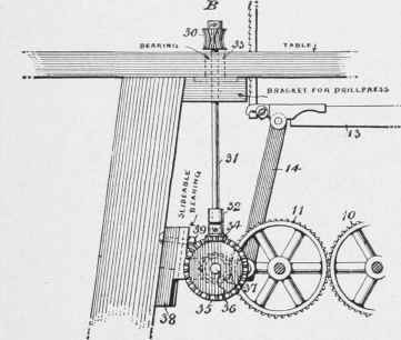
Fig. 52 - The router or molder.
Grater
The grater, shown in dotted lines at the lower right-hand corner of Fig. 45, consists of a box, in which is mounted to revolve in suitable bearings a shaft carrying on four extending arms two ordinary half round graters, soldered together, making a perfect circle. At the inner end of the shaft is fastened a gear-wheel, which meshes into the gear-wheel 8 on the rear hub 7. A suitable hopper is arranged at the top. This whole contrivance may be slid out and in horizontally and removed when not in use. A photograph of the machine in use is shown herewith.
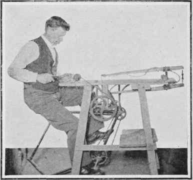
Fig. 53 - The complete machine in use.
Continue to:
My Books

