An Electrolytic Detector
Description
This section is from the book "Handy Man's Workshop And Laboratory", by A. Russell Bond. Also available from Amazon: Handy Man's Workshop And Laboratory.
An Electrolytic Detector
Those who have attempted to make a wireless detector have doubtless been slightly dismayed when it came to deciding on a certain type. Of course, there are many amateurs who like to make several types, but it is for those who desire to make but one detector, that this short description is written.
Of all the modern wireless detectors - the electrolytic, the carborundum, magnetic, silicon, audion - the electrolytic is given first place. It is very easily made and when made well requires very little adjustment or attention. The silicon and carborundum detectors being of the crystal type are fairly sensitive when correctly adjusted, but it is very hard to strike the maximum sensitive point. The audion is beyond the reach of most amateurs, because it employs platinum grids sealed in an electric-light bulb from which the air has been exhausted. The magnetic responder is a mechanical device, and is not very sensitive.
The sensitiveness of the electrolytic depends entirely upon the size of the platinum wire used for the "point," and the good workmanship and accuracy displayed in making' the detector. A photograph and drawing of this type is shown herewith, the cross-section lines being omitted in some places, in order to bring out the design better and clearer. The part A, Fig. 236, which will be called the standard, is made from a piece of brass i inch square and 1 1/2 inches long. A hole is drilled in each end and tapped for an 8/32-inch thread. A 1/8-inch brass rod 1 3/4 inches long is threaded its whole length, and screwed in one end. The part B is made from square brass tubing, 1/4 inch inside and about 1 [6-inch walls. There should he no side motion, turning to the left or right. It is important that this piece should fit snugly over part A. A square piece of sheet brass is to be soldered on one end, and a hole drilled exactly in the center. The arm C, which is soldered to piece B, is made 1/4 by 3/8 by 1 1/8-inch, one end being cut and drilled as shown. To hold the platinum wire, or point, a point holder is made from 1/8-inch rod about 1 1/8 inches long. One end is threaded with an 8 32inch die, and the other end is tapped to hold a 4/32-inch machine screw. A 1 1/4-inch piece of 3/8-inch round brass is tapped at one end for an 8/32-inch screw. The other end must be turned to a diameter that can be threaded with an 8/32-inch die. A small nut, which may be conveniently obtained from a dry cell, is fitted on the threaded portion.
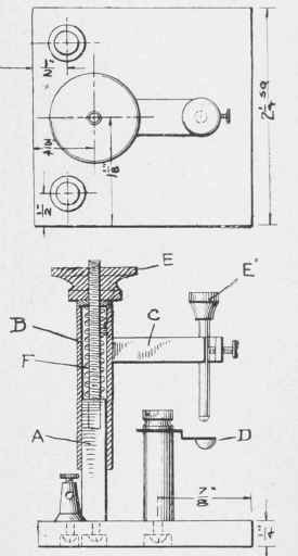
Fig. 236 - Plan, side and sectional views of the detector.
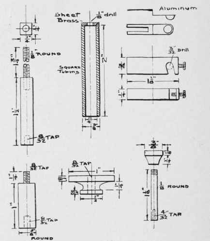
Fig. 237 - Details of the detector.
The small cup D, which is to be made of aluminium, is formed by hammering a cup-shaped depression in a piece of thin sheet aluminium. It need not be larger than 1/4 inch or 3/8 inch wide and 1 inch long. A slot is cut in the end opposite the cup. and is made wide enough to permit its being- fastened under the nut on the small standards. The thumb nuts, E E', are made from hard rubber, and may be turned to any desired shape. The larger one will have to be threaded to go on the rod of the standard. A. A small spring, shown at F, can be made from a brass wire.
If a glass cup, to hold the acid, is preferred, it may be made by sealing a platinum wire-in a small piece of glass tubing. The platinum wire may be soldered to a strip of brass, which in turn may be fastened under the nut on the standard. As regards the size of platinum wire to be used, 0.0001 inch is a very good size, and will work very delicately indeed. Of course, there are both finer and coarser wires that will work also, but the size mentioned gives excellent results and is moderate in price.
The assembling of the detector is made clear in Fig. 236. The position of binding posts, kind of base, and other details may be altered to suit the taste of the maker. The connections are shown in the small diagram. Fig. 238. A being the potentiometer or variable resistance, B the phones, C the battery; the tuning coil not being shown.
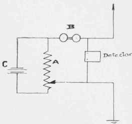
Fig. 238 - Diagram of the electric connections.
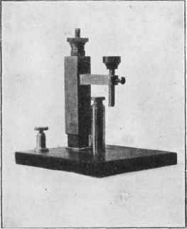
Fig. 239 - General view of the electrolytic detector.
Continue to:
My Books

