How To Cut A Cam Groove With A Lathe
Description
This section is from the book "Handy Man's Workshop And Laboratory", by A. Russell Bond. Also available from Amazon: Handy Man's Workshop And Laboratory.
How To Cut A Cam Groove With A Lathe
The accompanying illustration, Fig. 141, shows how a cam groove was cut in a drum cam by means of an improvised milling attachment on a lathe. The problem was to duplicate a cam which had previously been cut. This was used as a pattern or form to guide the milling cutter while cutting the blank. The form A with the blank B were mounted on an arbor C, and placed between the lathe centers. They were connected to the face plate by means of a dog D. An arm E was bolted to the carriage, and was provided with a roller to engage the cam groove in the form. The carriage was disconnected from the feed screw, so that as the form revolved it would be fed by the roller and cam groove. A pulley K was mounted at the head of the lathe bed, and a cord running over this pulley was provided with a weight at one end, while its other end was attached to the carriage. In this way a constant tension in the direction of the headstock was maintained. On the cross-feed slide a bracket F was mounted, and this carried a shaft fitted with a pulley G. The fatter was belted to a wide pulley H on a separate countershaft above the lathe. The pulley H was in reality a drum long enough to accommodate the belt as the carriage traveled across the face of the drum which was to be cut. The shaft of pulley G was provided with a socket to receive an end mill I. The latter was rotated at a suitable speed, by its connection with the pulley H, to cut the cam groove while the carriage was moved slowly toward the head-stock by the rotation of the form. The lathe was geared down to its lowest speed, and belted to a small pulley on the countershaft.
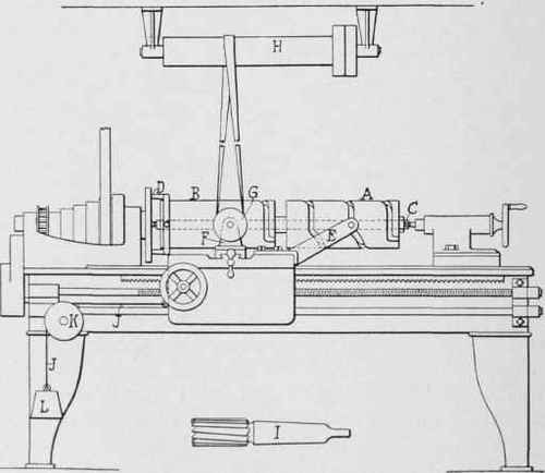
Fig. 141 - Cutting a cam groove with a lathe.
Continue to:
My Books

