


Through Girders
Description
This section is from the "Plate Girder Construction" book, by Isami Hiroi, C.E.. Also see Amazon: Plate Girder Construction.
Through Girders
Nearly all that has been said thus far about the deck girders applies equally well to through girders. Since it is not possible in a through girder to have top lateral bracing, particular attention should be paid to give lateral stiffness to the top flanges. This is done by connecting the top flanges with the floor beams by stiff plates, as shown in fig. 4, PL I. In case the floor beams are so spaced that the ratio of the width of the top flange plate to the distance between them exceedes 12, the allowable unit stress in the flange should, as explained on page 49, be reduced by the given formula.
Since the load now travels between the girders, and is transmitted to the web through floor beams, the rivets connecting the flanges with the web need to be proportioned only for the horizontal stress.
Though girders are sometimes constructed without floor beams or stringers, heavy cross-ties resting directly on angles riveted to the web, as shown in fig. (22).
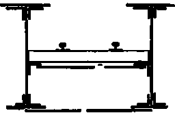
Fig. 22.
Bed Plates And Anchoring
Bed plates should be so proportioned that the maximum pressure on the masonry shall not exceed a certain amount, depend-ing upon the kind of masonry. Pressures of 250-300 lb6. per square inch can usually be allowed on good coping.
Bed plates should bo made so thick that the pressure will be uniformly distributed under its entire area.
For plate girders it is sufficient to have a ⅞" plate stiffened by a bar riveted on each side as shown in plate II.
The maximum end reaction, with proper allowance for impact, we have already found (p. 61) to be 75,800 lbs. Taking the allowable pressure on the masonry to be 300 lbs. we have for the required area of our bed plate75,800/300 =253 square inches.
Hence we have a bed plate 17¬Ã--16"=276 square inches.
In girders longer than about 70 feet, it is necessary to provide one end with a nest of rollers, but in shorter spans a mere sliding arrangement is sufficient. This is done by slotting the anchor bolt holes in the girder flange, enough to accomodate the forward and backward motion of that end of the girder, due to the extreme change of temperature, which may be usually-taken at 150°. The co-efficient of expansion of iron is about .000007 for 1° Fahrenheit. Consequently, for 50 feet girders we slot the bolt hole 50' Ã-- .000007 Ã--150° Ã--12" = or about1/1000 part of the entire length. The diameter of anchor bolts varies somewhat with the spare of girder and can be conveniently obtained by the following emperical formula:
d=«+ S/80.
In which d is the diameter of the bolt in inches and S the span in feet.
The depth to which the bolt is to be imbedded in the masonry, in case of a good strong coping, need not exceed 6 times its diameter.
For a 50 foot girder the bolt is l⅛inch in diameter and holes in one end of the girder are made 1¬ inch diameter 2nd elongated to 1⅞ inch.
Anchor bolts are fixed in masonry either by pouring molten lead or packing cement into the hole. The bolt should be enlarged toward the bottom and barbed by forging, or an ordinary bolt may be forked and wedged in order to obtained good hold on the masonry.
Continue to:


My Books

