


Web Stress. Part 6
Description
This section is from the "Plate Girder Construction" book, by Isami Hiroi, C.E.. Also see Amazon: Plate Girder Construction.
Web Stress. Part 6
According to what has already been said, the absolute maximum moment occurs when the center e of the girder lies midway between the perpendiculars through Y, and the load nearest to it, and is found under that load viz. r. I, shows the girder in such a position. Let fall from the ends of the girder perpendiculars cutting the sides of the polygon in points 1 and 2; join 1, 2. The maximum vertical distance between the line 1, 2 (called the closing line), and the sides of the equilibrium polygon, multiplied by the horizontal force represented by the pole distance, gives the maximum bending moment. Thus we find the maximum vertical distance to be at r, and which measures 11.65 feet. But the horizontal force has already been taken at 50,000 lbs., hence the maximum moment is equal to 11.65Ã--50,000=582,500 ft. lbs.
The maximum moments at the center and at e differ very little from this absolute maximum, and consequently they will be assumed to be alike.
Shift the span now to the right till the second driver comes over the point c, as shown in position II. Let fall the perpendiculars; join 3 and 4, and measure the maximum vertical distance between 3, 4, and the polygon. This we find to be 10.1 ft. Hence the maximum moment at c is equal to 10.1Ã--50,000=505,000 ft. lbs.
In the same way, by bringing the second driver over points a and b, as shown by positions III and IV, we obtain the maximum moments at these points. These we find to be:
At b 7.8 Ã-- 50,000=390,000 ft. lbs. " a 4.26Ã--50,000=213,000 " "
The total maximum moments at every point of the girder will evidently, when plotted, give the shape shown in Fig. 13, in which the lower curve is a parabola,and due to the dead load. The sum of the ordinates at any point on both sides of the horizontal line gives the total maximum moment at that point. Thus we have for the total moments at several points:
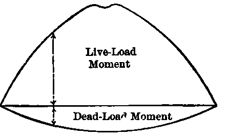
Fig. 13.
Dead. | Live. | Total. | |||||
At a | 55,100 | + | 213,000 | = | 268,100 | ft. | lbs. |
b | 98,000 | + | 390,000 | = | 488,000 | " | " |
c | 128,60C | + | 505,000 | = | 633,600 | " | " |
d | 147,000 | + | 582,500 | = | 729,500. | " | " |
e | 153,100 | + | 582,500 | = | 735,600 | " | " |
In determining the sectional area of flanges we will, as already said, leave the web plate out of consideration, and suppose that the flanges alone resist the bending moment, mainly for the reason that the part which the web contributes to the flange section is inconsiderable, as seen in the following calculation:
Moment of inertia of a web=bh3/12:

Assuming that h=h0, we obtain A1=bh/6 i e., the sectional area which the web contributes to the flange is but 1/6 of its own, which is certainly a very small amount, seeing that the thickness of the web is usually not more than ⅜ inch.
The depth of girder is more or less a matter of judgment for each case. For a given case one can find the most economical depth by few trials, by bearing in mind that the increase of depth increases the weight of web and stiffeners, while it decreases the flange areas, and vice versa. The depths usually vary from 1/9 to 1/12 of the span, according to the lengths of the latter; the shorter the span the more nearly the ratio to 1/9, and the greater the span, to 1/12.
Our attention will be confined entirely to the construction of parallel flanged girders, as curved flanges are rarely used on account of the much increased cost of construction.
It may be here remarked that it is usually only between spans of 50 and 80 feet that plate girders can be advantageously used, although spans up to 100 feet are sometimes constructed. For spans less than 15 feet solid rolled beams, and for spans greater than 80 feet, open girders are usually used.
We will fix the depth of our girder at 4 feet 6 inches. When we have one or more plates on the flanges we can, without much error, assume the distance between the centers of gravity of the flanges to be equal to the distance back to back of the flange angles, and take this as the effective depth of the girder.
As the flange section increases, the effective depth evidently varies more or less, but we can assume it to be constant throughout; at least we are on the safe side by doing so.
To find flange stresses we have now but to divide the maximum bending moment already obtained by the effective depth. Thus we obtain:
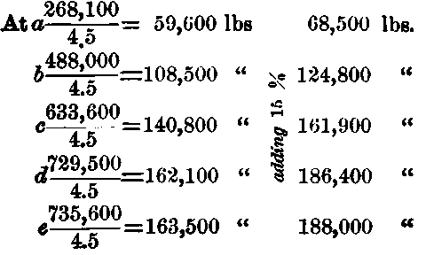
This addition of 15% is to provide to a certain extent for the impact which the moving load traveling over the girder brings about.
The actual amount of stress produced by the moving load like a locomotive is not possible of accurate determination. The imperfect condition of the track causes the moving load to produce shocks, and then again the centrifugal force of the unbalanced weights of driving wheels, which act like a hammer with repeated blows,* as well as the vertical component of the thrust of the connecting rod of the locomotive, produce stresses not always possible of accurate determination.
Continue to:


My Books

