Centrifugal Pumps
Description
This section is from the book "Workshop Receipts For Manufacturers And Scientific Amateurs. Supplement Aluminium To Wireless", by The Chemical Publishing Co.. Also available from Amazon: Workshop Receipts For Manufacturers And Scientific Amateurs.
Centrifugal Pumps
These pumps have in late years made considerable advances both in design and performance, and in favour as against plunger pumps, for many purposes. They are now used for such varied work as for irrigation schemes, sewage disposal, high pressure fire jets, and for feeding steam boilers under any required pressure, and for many other purposes. They are also extensively used for pumping other liquids than water. It is not proposed here to enter into the design of the revolving runner or impeller, or its width or diameter, these being matters that concern the maker only. In all makes of centrifugal pumps there are one or more revolving impellers, whose width depends partly upon the makers' general design, and upon the amount of water or other liquid being dealt with. The diameter depends upon the head against which the pump has to force the water, and upon its number of revolutions per minute. Therefore it should be clear that if a number of different centrifugal pumps were opened out and compared, there would appear to be very considerable differences in design, even as regards the relation between the diameters and the widths, etc; our concern here is to know how they work, and how to find the reason of any fault apparent or real that might arise and how to effect an improvement.
Fig. 25 shows a view of a revolving impeller, with its side taken away to show the blades clearly, together with a phantom view of the stationary blades or the diffuser that surrounds the impeller. It shows the patent can-struction used in their pumps by The Rees Roturbo Mfg. Co. Ltd., and it results in giving a pump that has all the advantages due to ordinary centrifugal pumps, with the added addition that these pumps can deal with any head below that for which they were designed and yet will not overload the driving motor or engine. This effect is really due to the design of impeller, it being a revolving pressure chamber, i.e., the water is under a pressure while in the impeller, resulting in self-regulation. An ordinary design of impeller under the same conditions would certainly cause any electric motor driving it to overheat, and probably burn out.
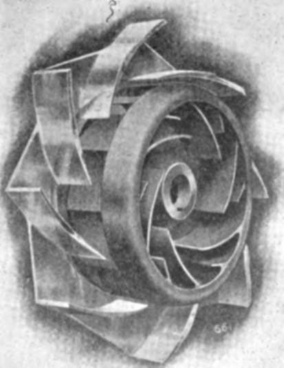
Fig. 25.
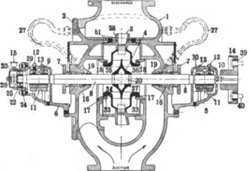
Fig. 28.
Fig. 26 shows a section of one of these pumps, and the names of the different parts are as follows :-
1 ;Casing.
2 ;Head.
3 ;Diffuser.
4 ;Impeller.
5 ;Tail bearing bracket (Drive).
6 ;Tail bearing bracket (Thrust).
7 ;Gland.
8 ;Shaft.
9 ;Tail bearing box (Thrust).
10 ;Tail bearing box (Drive).
11 ;Oil rings.
12 ;Special Screw.
13 ;Oil well covers.
14 ;Coupling.
15 ;Lubricator.
16 ;Packing;
17 ;Casing rings.
18 ;Impeller rings.
19 ;Gland bush.
20 ;Key for impeller.
21 ;Key for coupling.
22 ;Thrust bearing housing.
23 ;Thrust bearing cap.
24 ;Thrust bearing.
25 ;Thrust bearing lock nut.
26 ;Thrust bearing jam nut.
27 ;Water sealing pipes.
28 ;Diffuser side plate.
29 ;Tail bearing bracket cap
(Thrust).
30 ;Tail bearing bracket cap
(Drive).
33 ;Adaptor.
34 ;Impeller lock.
35 ;Impeller lock ring.
36 ;Shaft collar.
37 ;Shaft collar ring.
38 ;Foot.
39 ;Coupling bushing.
40 ;Coupling pins.
61 Diffuser fixing screw.
The pump is a single stage, with a double entry impeller, i.e., the water can enter the impeller on both sides at once. Fig. 27 shows an outside view of another single stage, double entry pump, and shows clearly the great difference that can exist in the proportions of width to dia-meter,and which depends upon the duty and speed. Fig. 28 shows the various parts of a pump by the same makers designed to meet the demand for a simple and cheap type of pump of moderate output; these also have the self-regulating properties; it is a two-stage pump, and the various part names are as follows:
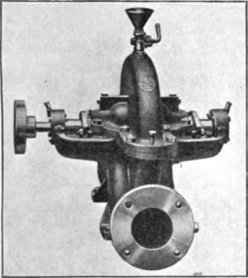
Fig. 27.
1 ;Casing.
2 ;Head.
3 ;Water passage.
4 ;Impellers.
5 ;Impeller lock-nut.
6 ;Grub screw for (5). Now to get a high pressure on these pumps without going to excessive speeds or diameters of impellers, a number of impellers are used in series which means that the liquid being pumped is taken by the first impeller, then passed through the second, then the third, and so on. Each impeller adds a certain head to the water and this multiplied by the number of impellers gives the total pressure that the pump will supply. Fig. 29 gives a diagram showing the direction of the water flow through four of these impellers, each impeller being of two stages, so that the final result is as though eight impellers were used of one stage each. It should be noted that each impeller here is virtually two single stage impellers of single entry, put back to back, with a separating wall between the two stages. Fig. 30 gives a cross section of such an eight stage pump, and the various parts numbered are as follows :
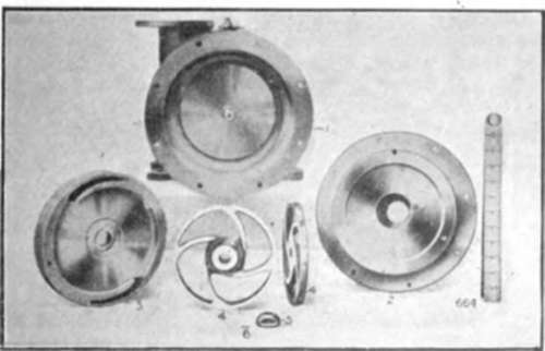
Fig. 28.
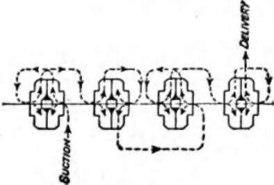
Fig. 29.
1 ;Casing.
2 ;Head.
3 ;Diffuser.
4 ;Impeller.
5 ;Tail bearing bracket (Drive).
6 ;Tail bearing bracket (Thrust).
7 ;Gland.
8 ;Shaft.
9 ;Tail bearing box (Thrust).
10 ;Tail bearing box (Drive).
11 ;Oil rings.
12 ;Special screw.
13 ;Oil well cover.
14 ;Coupling.
15 ;Lubricator.
16 ;Packing.
17 ;Casing rings.
18 ;Impeller rings.
19 ;Gland bush.
20 ;Key for impeller.
21 ;Key for coupling.
22 ;Thrust bearing housing.
23 ;Thrust bearing cap.
24 ;Thrust bearing.
25 ;Thrust bearing lock-nut.
26 ;Thrust bearing jam-nut.
27 ;Water sealing pipes.
28 ;Diffuser side plates.
29 ;Tail bearing bracket cap
(Thrust).
30 ;Tail bearing bracket cap
(Drive). 33 Adaptor.
39 ;Coupling bushing.
40 ;Coupling pins.
41 ;Sleeve for shaft.
42 ;Intermediate sleeve for shaft.
43 ;Outside clamping collar.
44 ;Inside clamping collar.
45 ;Split ring.
46 ;Water passage.
47 ;Water passage bush.
48 ;Wearing ring.
49 ;Air cock.
50 ;Eye bolt.
51 ;Forcing screw.
52 ;Oil plug.
53 ;C's'k screw for sideplate. This principle of obtaining high pressures by putting the impellers in series can be carried out to obtain any pressure that modern engineering requires. Fig. 31 shows a view of a 12 stage pump driven by an electric motor, the casing of the pump is jointed on the horizontal line, so that it may readily be assembled, or taken to pieces if required Now enough has probably been given here to show the general principles of working and construction of centrifugal pumps. The advantages of centrifugal pumps over plunger pumps are several, in the first case if a centrifugal pump be working on a pipe line without an air chamber or other safeguards, and the outlet be closed quickly, with the pump left running, then no harm is done at all, the pump merely runs on taking less power, but if the same thing be attempted with a plunger pump it promptly developes into a fight between the pump and the pipe line, with the chances greatly against the pipes. This means that much less attention is required on that score by the centrifugal. There is considerably less wear and tear, and less noise, with a centrifugal than with a plunger pump, and less floor space is required by the centrifugal. For high pressure and moderate amounts of water the size and weight of a centrifugal is very considerably less than that of a plunger pump.

Fig. 30.
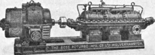
Fig. 31.
Like all other machinery it pays to give attention to the proper fixing, erection, and running of centrifugal pumps, and the following notes on such points supplied by Messrs. Rees Roturbo Mfg. Co. Ltd. apply equally well to any make of centrifugal pump.
Useful Instructions for Fixing and Running. General.-Pumps are designed and supplied to be fixed on foundations constructed of a solid block of concrete, brickwork or masonry, or steel construction. They should not., unless as a temporary measure, be mounted on timber without first consulting the makers.
Continue to:
My Books

