Tyres. Fitting Solid And Cushion Tyres
Description
This section is from the book "Workshop Receipts For Manufacturers And Scientific Amateurs. Supplement Aluminium To Wireless", by The Chemical Publishing Co.. Also available from Amazon: Workshop Receipts For Manufacturers And Scientific Amateurs.
Tyres. Fitting Solid And Cushion Tyres
These, when merely fastened on to a wheel by cement, or by means of the two ends of an internal wire being hooked over each other, are not entirely satisfactory, and it is considered that the two patent methods detailed below will be of interest and real use. The "North Pole n solid tyre has embedded in it a length of hard tempered Spiral Steel Wire, in the centre of Rubber Tyring, and the binding or constricting action of the Spiral Wire on a steel joining pin inserted half way into each end, in order to join the two ends together, Fig. 214.
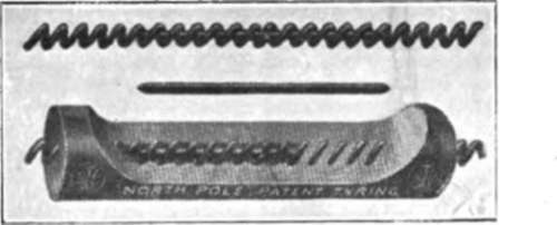
Fig. 214.
The effect of inserting the "joining pin " inside the spiral is a very slight enlarging of the latter, but upon attempting to withdraw the " joining pin " the bore of the spiral tends to contract and thus rigidly binds on the "joining pin," which cannot possibly be withdrawn.
Method Of Fitting. Measuring
Place Tyring round the rim to be fitted to find its circumference, then cut off short (to allow for necessary stretch) on basis of lin. for every 25in. of Tyring required.
The following are the lengths of Tyring required for Standard size wheels :-
Wheel diameters-5in., 6in., 7in., 8in., 10in., 12in., 14in., 16in., 18in., 20in., 21in., 23in., 25in.
Lengths of Tyring-151/2in., 181/2in., 211/2in., 241/2in., 301/2in., 361/2in., 421/2in.,
48in., 54in., 60in., 63in., 69m., 75in.
Cutting Wire
(To apply when not using the " North Pole " Cutting Tool.) After cutting the rubber, place over a thin piece of steel and sever the embedded wire by the aid of the hammer and chisel. After this, the ends of the wire should be trimmed off flush with, or if possible slightly inside, the rubber.
Joining
(To apply only when not using the " North Pole " Joining Machine.) Place one of the steel joining pins supplied in a vice leaving half of it projecting, and then force one end of Tyring over projecting half of pin. Next place this end of Tyring in the vice, and force the other end over the remaining half of the pin.
N.B.-This operation is made easy by using " Gripping " Pliers and hammer. Whilst gripping the Tyring the pliers are hammered in the direction of vice, enabling operator to make a joint with the ends of the Tyring in close contact with one another.
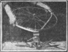
Fig. 215.
Fitting To Rim
The tyre should be stretched all round as evenly as possible in fitting. Place the tyre in the rim, joint first, then stretch with hands as far as possible. The last portion can be fitted by inserting a thin spindle (held in vice) between tyre and rim and revolving as Fig. 215. Make one complete revolution to distribute stretch, before withdrawing spindle.
Alternately the last portion can be fitted by the aid of a strap or tape inserted round tyre and used as a handle to stretch it on.
Any twist which the tyre may take in fitting must be corrected.
Gripping Pliers
To obtain a secure grip and to protect tyring, it is advisable to insert a piece of thick cloth (a piece of old cycle cover will do) between rubber and pliers. The tyring should be gripped about 1in. from the end, to allow pin to enter freely.
When joining large section tyre, the shanks of the pliers can be wrapped together with tape to lessen the jar from the hammer.
Important
Tyres must not be rolled on to the rim and left in twisted condition. Attention to this is most important.
Standard sizes of tyring from 3/8in. to 1 Jin. diameter are obtainable, and uses for this other than for prams and bath chairs may present themselves.
The " John Bull " Cushion Tyre is fitted and held in a different manner, it having a large central hole through which a loose spiral wire passes. The ends of this wire are interlocked with each other as explained below.
In making up tyres, the rubber has to be compressed so that the ends of the spiral wire can be interlocked, when the rubber is released so as to form the complete tyre.
1. ;With a wet, sharp knife cut off exact length of tyring required. See that the cut is quite clean and properly bevelled from ribbed tread inwards, as these two factors are essentials of a good join!.
2. ;With the cutting pliers cut off exact length of spiral wire required.
3. ;Thread spiral wire into hole of tyring, until about 11/2in. of wire projects : retain in this position with one of the two steel clamps provided, see Fig. 216.
4. The other end of the spiral wire is now a few inches within other end of rubber tyring, and the problem is to compress rubber back until cut length of spiral wire projects about 11/2in. To accomplish this, insert a loose length of spiral wire (about 1ft. long) into hole and twist to left so that it engages with spiral wire inside. Then fasten loose end of spiral wire in a vice or by other convenient means and with both hands pull or compress back rubber until liin. of measured length of spiral wire projects, Fig. 216. Retain this with other steel clamp and disengage the loose one foot of wire. (N.B.-This 1ft. of wire can be interlocked into measured length of wire before threading in the tyring, if preferred.)
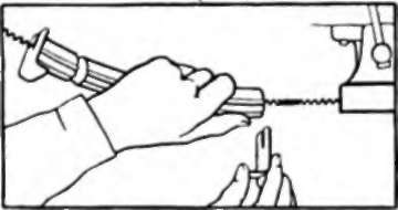
Fig. 216.
5. ;Taking in both hands rubber tyring with its spiral wire projecting 1 Jin. both ends, twist back one end of tyring one complete turn, interlock first coil of one end of spiral wire into second coil of other end of spiral wire and rotate or " twist-in " until two coils are interlocked. Finish oft by untwisting tyring back to normal- this will interlock a third coil, Fig. 217.
6. ;Now, take off both steel clamps, when the relieved compressed rubber will spring forward, entirely covering spiral wire and forming a perfectly flush, neat and practically watertight joint. If rubber ends are now pulled or bent apart sufficiently to enable them to be coated with solution, the joint, when pressed together again, becomes absolutely watertight. (N.B.-The use of solution on joint is an extra aid to water-proofness. A good joint can, of course, be made without solution if desired.)
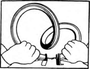
Fig. 217.
Fitting To Wheel
Closely follow the same fitting instructions as for " North Pole " Tyring, that is, use the " North Pole " Fitting Tool, or proceed as follows :-
Place tyre on wheel, joint first, stretch on with hands as far as possible, then prise the remainder on with a steel chisel (held in vice), Fig. 215. Tyres must not be rolled on to wheel and left in twisted condition. To obviate this and to distribute stretch all round, make one complete revolution of wheel with chisel between tyre and rim.
This tyring is obtainable in sizes from Jin. to 11/4 diameter.
Continue to:
My Books

