Chapter XXXI. Continuous Distillation Under Atmospheric Pressure
Description
This section is from the book "Distillation Principles And Processes", by Sydney Young. Also available from Amazon: Distillation Principles And Processes.
Chapter XXXI. Continuous Distillation Under Atmospheric Pressure
Continuous distillation was first introduced on a working scale in Persia as far back as 1883. It is now very extensively applied in all modern refineries for the treating, not only of crude oils, but also of distillates, and for the making of lubricating oils and asphalt. This method can, in fact, be applied to practically all the operations ordinarily carried out in periodic stills, with the exception of those cases in which the residue is a solid material.
The continuous system possesses several advantages over the periodic, the chief of which are: - (a) increased throughput for plant of given size, with consequent lower depreciation charges; (b) much less wear and tear on the plant, owing to uniform temperature conditions, with consequent lower maintenance charges; (c) lower operating wages and working losses, and (d) lower fuel consumption. The comparatively recent introduction of tubular stills has made this system of distillation even more general.
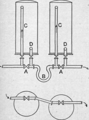
The earlier types of continuous batteries consist of simple stills of the kind described in the previous chapter, fitted merely with domes, vapour pipes, and condensers. The stills are arranged in series, as many as twelve or more being sometimes employed. They are usually all of the same dimensions, but as the volume of oil which has to pass through the later stills of the series is naturally relatively smaller, these are often constructed of smaller dimensions. They are set in cascade fashion with a fall of 9 inches or thereabouts between each still. In order to allow for expansion of the brickwork they are usually arranged in groups of three or four. They resemble the periodic stills previously described except in so far as regards the arrangement of the feed pipes. These are arranged so that the oil flows from one still to the next, throughout the series, the level of the oil in any one still remaining constant. By-pass valves a (Fig. 137) are fitted so that any one still can be cut out for repair without affecting the working of the bench as a whole. Expansion pieces b are usually fitted between each still. The inlet pipe c usually extends to the far end of the still, terminating near the bottom of the still. Both inlet and outlet pipes should be fitted with open tee-pieces at the end, or, if bends are used, then these must be provided with small holes on the top to act as gas vents, as otherwise vapour locks may form and interfere with the free running of the system. In this connection, too. it should be noted that all valves on the feed line should be of the gate type, as globe valves seem to give opportunities for vapour locks in the line.
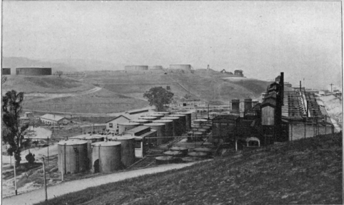
The main feed line should be of ample diameter, not less than 6 inches, better 8 inches or 10 inches, depending on the capacity of the bench, as the fall between successive stills is only a few inches. The stills are kept about 5/8ths to |rds full, and the oil should flow through regularly, each still being kept at a certain definite temperature. The working temperatures will depend naturally on the number of units in the bench, on the nature of the oil, and on the products being distilled off. The conditions should be adjusted so that the work is distributed regularly among the stills. If this is not done, then irregular running will result, owing to different pressures obtaining in various stills consequent on different rates of condensation in the coolers. One square metre of still heating surface may be taken to be capable of giving one ton of distillate per twenty-four hours.
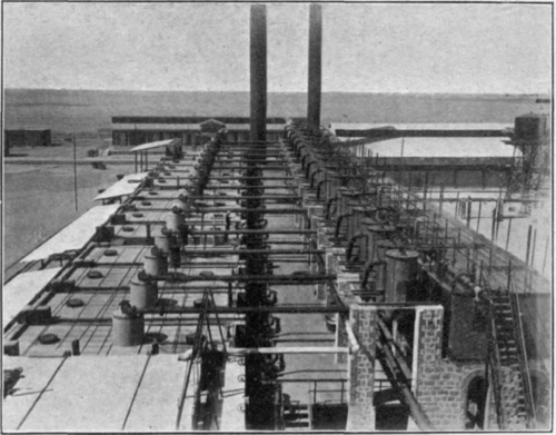
Fig. 136. - A continuous distillation bench.
The outflowing residue is usually allowed to flow through a heat exchanger in which it gives up its heat to the inflowing crude oil. These heat exchangers may be of various types. A usual form consists of a high vertical tank (Fig. 138) fitted with a nest of residue coils, provided with a float and gauge glass f for showing the level of the crude oil, with a water draw-off a, and with an outlet for the crude e at such a level that it will gravitate to the bench of stills. By keeping the oil at a constant level in this preheater, a steady flow of crude to the bench is assured.
In the case of crude oils which yield high percentages of residue, the crude oil in the preheater becomes sufficiently warm to allow distillation to begin. The preheaters are, therefore, often fitted with a vapour
Diagrammatic arrangement of Feed Pipes for Continuous Stills dome, pipe and condenser, and function as a still. They should be fitted also with safety valves. If a crude which contains any water is being handled, care should be taken that the temperature in the preheater never reaches 100° C, or otherwise the contents may foam over through the vapour pipe or safety valve.
A. Bye-pass Values C. Inlet Pipes
B. Expansion Bend D. Outlet Pipes
Fig. 137.

Fig. 138. - Crude oil preheater or heat exchanger.
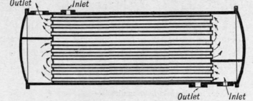
Fig. 139. - Tubular heat exchanger.
Tubular heat exchangers are also commonly employed. These are constructed on the lines of a tubular condenser, baffle plates being usually placed in the end chambers in order to direct the flow of residue through the tubes (Fig. 139).
Each of the stills of the bench is, in the simple types of plant, coupled direct to its condenser. As each still is kept at a constant temperature, it yields a distillate of constant composition. A simple battery of 5 stills working continuously on a crude oil of about .850 specific gravity taking off benzine and kerosene distillates would be operated in this way. The crude oil, after leaving the heat exchangers, would have a temperature of perhaps 90° to 100° C, but this would depend, naturally, on the percentage of residue left after distilling off the distillates. The percentage of residue may vary between very broad limits from as much as 95 per cent down to as little as 10 per cent, depending on the nature of the crude oil. The temperatures in the stills would be kept at about 130°, 170°, 220°, 260°, 300° C, the temperature of the vapours being 20° or 30° less. The distillates coming off would have specific gravity of about .750. .785, .810, .830, .850.
Continue to:
My Books

