Drains
Description
This section is from the book "A Treatise On Architecture And Building Construction Vol4: Plumbing And Gas-Fitting, Heating And Ventilation, Painting And Decorating, Estimating And Calculating Quantities", by The Colliery Engineer Co. Also available from Amazon: A Treatise On Architecture And Building Construction.
Drains
130. Drains should have a uniform pitch or fall throughout their length. The line of pipe must not have any part of it run on a level, nor should it be allowed to have any part of it sag below the general inclination, so that a pocket can be formed in which water will lie. The proper inclination or pitch to be given to drains varies with the diameter of the pipe, being greatest for the smallest diameter.
The inclination should be enough to give the water a velocity of about 275 feet per minute. A less velocity will fail to carry along the solids which usually accompany the water.
131. The proper fall for each size of pipe is given in the following table, 1 foot of fall being allowed for the length given under each diameter:
Table 6
Diameter..... | 2 | 3 | 4 | 5 | 6 | 7 | 8 | 9 | 10 | inches. |
Length to 1ft. of fall | 20 | 30 | 40 | 50 | 60 | 70 | 80 | 90 | 100 | feet. |
Thus, a pipe 3 inches in diameter should be laid with a minimum fall of 1 foot in 30 feet of length.
132. The proper diameter of the pipe to be used for a drain is a matter that requires careful consideration. The pipe should be large enough to carry off, within reasonable time, the largest quantity of water that will ever be turned into the drain; yet, it must not be so large that the ordinary flow of water will fail to float and carry along the refuse that ordinarily accompanies the water.
Thus, the quantity of water which would run properly in a 5-inch pipe would, if passed through a 9-inch pipe, be so shallow that it would not float and carry the refuse along. This may be seen by observing the difference in depth between the water in the 5-inch pipe, shown in section in Fig. 49, and the same quantity in the 9-inch pipe, shown in section in Fig. 50. In Fig. 49 the solids discharged from the water closets can easily be floated and carried along with the current without even touching the pipe. Since they do not touch the pipe and are submerged in the center of the moving water, it follows that they must move forward as fast as the water which surrounds them. In the 9-inch pipe, however, with the same quantity of water, the solids will touch the pipe, because the water is not deep enough to properly float them. The adhesion of the solids to the pipe will create such a resistance to their movement that the water will soon flow ahead and leave them behind, where they will remain until another flush comes and moves them forward a little further.

Fig. 49.

Fig. 50.
133. The velocity with which water will flow through a pipe will depend upon the degree to which it fills the pipe. This is shown by the diagram, Fig. 51. If the level of the flowing water is at D, and the length of the line D E is taken to represent the velocity of the current, then the velocity of a quantity of water which fills the pipe only to the level F will be represented by the line F G. The difference is largely due to the greater friction of the smaller stream, the proportion between the wet surface of the pipe and the quantity of the water being much greater at the level F than at the level D. It will be noticed that when the pipe is about three-fourths full the maximum velocity is attained.

Fig. 51.
A diameter of 4 inches is usually sufficient for a drain for an ordinary dwelling; if the rain pipes empty into it, a 5 or (3 inch pipe should be used.
134. Care should be taken to lay drain pipes in a straight line. If they are made of earthenware, every length of pipe should be cemented, thoroughly cleaned, and examined inside before proceeding with the next piece.
When laying earthenware pipe, care should be taken that no cement is left projecting inside the pipe as at x, Fig. 52.
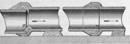
Fig. 52.
The inside surfaces of the pipe should lay flush and true as at y. All bends and curves should be of large radius. Right-angled branches and sharp turns should be avoided.
Drains should not pass under a dwelling if it can possibly be avoided. If the drain pipe passes through or under a foundation wall of a building, a liberal allowance must be made for the probable settlement of the wall. In new buildings, and upon made ground, the settlement is likely to be considerable.
135. Steam or very hot liquids should not be discharged into an ordinary drain. If there is much steam or hot liquids to be carried away, a special drain should be made for the purpose. They must never be discharged into a street sewer, unless the liquid is first cooled.
136. All drains should be provided with inspection pieces and cleaning holes, through which the interior of the pipe can be seen, and through which cleaning tools can be introduced. Care should be taken in locating these pieces or handholes, that sufficient room is provided around them to handle the cleaning tools.
Such an inspection piece is shown in Fig. 53. The cover A is secured by bolts, and is made air-tight by a gasket B. These fixtures should be located at each bend in a main drain, so that every part of the drain may be examined with a lamp and mirror when desired. The inspection piece shown in Fig. 53 is particularly adapted for placing at regular intervals of 75 to 100 feet along a straight underground drain, in which case it would be built in a brick manhole about 3 feet long by 2 feet wide.

Fig. 53.
137. Two bends, with an inspection hole and covers, are shown in Fig. 54. A is suitable for joining two horizontal drains, while B is suitable for a vertical and horizontal junction.
138. Drains should be flushed periodically to wash them clean and remove all accumulations of filth. To do this properly, a large volume of water is necessary, and it should be released suddenly. The flow should be sufficient in volume to completely fill the bore of the pipe, and the head should be great enough to insure a swift and forcible current.
Automatic flushing tanks for this purpose are constructed to receive and store the water from the roofs, and sometimes the water from the wash bowls and bath tubs is stored in a tank of this kind. When the tank becomes full, it discharges itself in a strong, steady stream, thus effectually scouring the drain to which it is attached.
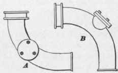
Fig. 54.
Continue to:
My Books

