Hot-Water Boilers
Description
This section is from the book "A Treatise On Architecture And Building Construction Vol4: Plumbing And Gas-Fitting, Heating And Ventilation, Painting And Decorating, Estimating And Calculating Quantities", by The Colliery Engineer Co. Also available from Amazon: A Treatise On Architecture And Building Construction.
Hot-Water Boilers
55. Boilers for domestic use are made either of copper, thoroughly tinned upon the inside, or of galvanized iron. They are usually set in a vertical position, but when circumstances require it, they can be operated horizontally. Boilers are also made double, one within another, to suit places where the water is drawn from two sources at different pressures, and where one water heater must heat the water in both boilers.
The size of boiler which should be placed in a residence is a matter of great uncertainty. Experience shows, however, that a 40-gallon boiler is usually sufficient for a house having one bathroom, and one sink, a set of wash tubs, and a wash bowl. If there be two bathrooms, a 50 or 60 gallon boiler should be used. It is good policy to have the boiler a little larger than necessary, rather than small, particularly if the pressure be low.
Boilers may be covered with neat wooden lagging, composed of strips of pine or hard wood, 1 1/2 inches to 2 inches wide, 3/4 inch or more in thickness, tongued and grooved, and confined by brass or galvanized iron bands. This will prevent the large waste of heat which occurs from radiation, and which goes far to make the kitchen uncomfortably warm.
Safety valves are not necessary when the boiler is connected directly, without the intervention of a check-valve or a reducing valve, to the street mains, or to the pipe from a tank, because the expansion of the water in the boiler is relieved by forcing a small amount back into the supply pipe. Where that method of relief is prevented by check-valves or other devices, safety valves must be used.
A vacuum valve must be attached, if a copper boiler is likely to be emptied and to have a vacuum formed within it; because the pressure of the atmosphere upon the outside will crush it, unless the vacuum be destroyed. A boiler which is supplied with an expansion pipe, i. e., the pipe which runs from the hot-water distributing pipe to a point over the supply tank and has its end open to the atmosphere, needs neither a safety nor a vacuum valve.
Boilers should be tested by warm water pressure to 150 pounds per square inch for general service. A test of 100 pounds per square inch is sufficient for working pressures of 30 pounds or less. For extra heavy working pressures, the boilers should be tested to double the working pressure, or to at least 100 pounds more than the working pressure.
The consequences of the explosion of kitchen boilers are likely to be very serious, and the architect should insist that the manufacturer test every boiler to a proper test pressure, and guarantee it to endure that pressure.
Iron boilers are galvanized after they are riveted together. The interior can be examined by pushing a lighted candle inside and looking through the pipe holes.
Boilers which are constructed with a single line of rivets in the longitudinal seam, are called single riveted and are suitable for moderate pressures only. Those having two lines of rivets, in zigzag or alternate order, are called double riveted and are suitable for heavy pressures. A single row of rivets is sufficient to secure the head or the bottom.
56. The proper mode of connecting up vertical boilers is shown in Fig. 27. The cold-water pipe X should enter at the top of the boiler and end at the line a b, which should be about 3 inches above the level of the water-back WB. When the pressure is shut off, the water is likely to be drawn out of the boiler by the. opening of a faucet at a lower level, as at C. The pipe XX1 then acts as a siphon, and will run the water out until its level falls to the end of the pipe X1. If X1 extends to the line c d, the waterback will be drained, which is dangerous, for unless the fire is drawn, the waterback will become overheated, and when the cold water is turned on, it will be likely to crack or explode. All danger from siphoning can be avoided by drilling a small hole, about 1/8 inch, in the pipe as at B. The hot-water pipe A is connected at the extreme top part of the boiler.
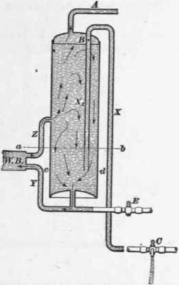
Fig. 27.
The direction of the circulation is shown by the arrows. Connections are made to the waterback by two pipes Y and Z. The pipe Y should be connected to the bottom of the boiler, and should be inclined upwards towards the water-back. The pipe Z receives the hot water from the waterback, and should be inclined upwards towards the boiler. It should be connected to the boiler at a point not less than one-third the height above the bottom, and it should be at least 1 inch internal diameter for a 40 to 60 gallon boiler.
A blow-off cock, to remove mud and sediment, should be provided, as at E. This may empty into a sink, or may be connected to the waste pipe on the house side of a fixture trap.
Boilers connected in this way require considerable time to heat their entire contents so that hot water will readily appear at the faucets.
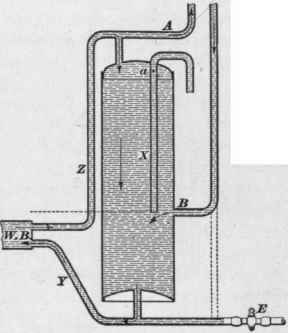
Fig. 28.
57. When it is desired to get hot water without delay after starting up the fire, another system of hot-water connections is resorted to. This is shown in Fig. 28. The pipe Z is connected directly to the hot-water distributing pipe A, as shown. Thus, the hot water as it comes from the water-back can go direct to the fixtures, or if none is wanted, it can go into the boiler.
When hot water stands in the pipes for any considerable time, it cools off, and several gallons of cold or lukewarm water must be drawn from the faucet before hot water appears. This is always annoying, and when water is scarce, it is very troublesome. To secure hot water at each fixture promptly upon the opening of the faucet, a return or circulation pipe must be used. This pipe is joined to the hot-water supply pipe near each fixture, and it should always be one or two sizes smaller than the hot supply pipe. The return branches are united to a descending pipe, which enters the boiler at B, Fig. 28, about one-third up. It is not good practice to connect the return pipe to the extension of pipe Y as shown by the dotted lines.
Check-valves should not be employed in this return pipe, because the circulating current is too weak to operate them.
The hot water rises in A and returns in B, thus maintaining a circulation sufficient to keep A filled throughout its entire length with hot water of satisfactory temperature.
Continue to:
My Books

