Traps
Description
This section is from the book "A Treatise On Architecture And Building Construction Vol4: Plumbing And Gas-Fitting, Heating And Ventilation, Painting And Decorating, Estimating And Calculating Quantities", by The Colliery Engineer Co. Also available from Amazon: A Treatise On Architecture And Building Construction.
Traps
108. A trap is a device which allows the free passage through it of liquids and such solid matter as the liquid may carry with it, but which prevents the passage of air or gas in either direction.
The simplest form of trap is shown in Fig. 33. It consists of a downward loop in a horizontal pipe. The loop is filled with water while the pipe at each side of it may be empty. Whenever water is run through the pipe, enough will be retained to fill the bend and prevent air or gas at atmospheric pressure from passing. If the air has sufficient pressure it may force the water down upon one side of the bend and up upon the other until the air can escape past the bend at B, and bubble upward through the water. The difference between the level of the water when quiet as at A, and the point B, is called the seal of the trap.


Fig. 83.
109. Fig. 33 exhibits the principle of the class called round-pipe, or Du Bois traps. The usual forms of round pipe traps are shown in Fig. 34.
A is known as an S trap. It is used chiefly under fixtures where the waste pipe descends to the floor.
B is a half S or P trap. It is used chiefly to join fixtures to a horizontal waste-pipe branch.
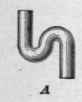


Fig. 34.
C is a three-quarter S trap. It is used chiefly to join fixtures to a Y branch in a soil pipe where the distance between the trap and the branch is short.
D is a lying or running trap. It can only be used on a horizontal waste pipe. It is often used as a bath trap, being placed under the floor.
E is a hunchback trap. This form is used on a vertical pipe where it is desired to have the inlet and outlet in the same straight line. It is not used as much in plumbing as the other forms.
110. In Fig. 35 is shown a bottle trap. This trap is only used under fixtures, such as sinks, baths, basins, or wash tubs, never under water closets. The inlet pipe A is attached to the fixture, and the outlet pipe B joins the waste pipe D, of which the part C forms the back-vent. G is an overflow pipe. It is next to impossible to unseal this form of trap, although some of the seal may be lost by siphonage. Its chief objections are that filth is liable to accumulate in the bottom of the trap and grease upon the top of the water and in the chamber E, and that the water cannot be completely renewed every time the fixture is used.
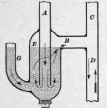
Fig. 35.
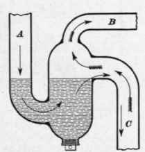
Fig. 36.
111. In Fig. 36 is shown a modification of Fig. 35. It is more direct in action than Fig. 35, and is more easily unsealed. It, however, overcomes the danger of drain air entering the building through unseen holes in its interior, as would occur if the tube A in Fig. 35 were corroded within the chamber E. Care must be taken when attaching an overflow pipe, for instance from a wash basin to any form of trap, particularly to those of the pot or bottle formation, to have the proper seal.
In Fig. 36 the trap receives waste water from the fixtures by the pipe A. B is the back-vent pipe, and C the waste pipe. The arrows with feathers show the direction of the natural air currents in the drainage system.
112. In Fig. 37 is shown a ball trap, in which a trap is combined with a check-valve. The ball valve c prevents the return of either liquid or gas, and the liquid around the ball keeps the seat gas-tight.
The specific gravity of the ball is but slightly greater than that of water, so that a very slight head of water in B will raise the ball. This trap is particularly suitable for clean-water fixtures, such as basins or baths, which are liable to remain unused a sufficient length of time to permit the water in the trap to become evaporated and its seal consequently lost. In such a case, the ball will form a nearly gas-tight joint with its seat and prevent the passage of drain air to the building.

Fig. 37.
This trap, and all other traps having the water way-restricted by mechanical appliance, such as check-valves, are liable to chokage by accumulating hair, small pieces of rags, sponges, and even matches.
The position of the ball when water passes through the trap is shown by dotted lines. It cannot enter the trap outlet pipe, as the space between the lip a and the handhole cover D is too small.
113. A bell trap is shown in Fig. 38. In it the seal is formed by the bell a which is suspended from the strainer b.
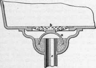
Fig. 38.
dipping into a small pool of water formed by the waste outlet c projecting into the trap casting. The chief objections to the bell trap are:
1. It soon becomes choked by sediment lodging in the bottom, which cannot be removed without lifting off the bell. This, for the time being, permits open communication between the drains and the building.
2. It is easily siphoned.
3. It is quickly evaporated if not used.
In fact, the bell trap has no redeeming features, and should be abolished in house-drainage systems.
Continue to:
My Books

