IV. Analysis Of Trus5es; "Method Of Joints.". Part 5
Description
This section is from the book "Cyclopedia Of Architecture, Carpentry, And Building", by James C. et al. Also available from Amazon: Cyclopedia Of Architecture, Carpentry And Building.
IV. Analysis Of Trus5es; "Method Of Joints.". Part 5
* As already stated, methods for determining reactions are explained in Art. 37; for the present the values of the reactions in any example will be given.
We are now ready to draw polygons for the joints; we may begin at the right or left end as we please but we should bear in mind that the polygons must be clockwise because the polygon for the loads and reactions (BCEFB) is such an one. Beginning at the right end for example, notice that there are three forces there, the right reaction, de and do. The right reaction is represented by CE, hence from E draw a line parallel to de and from 0 one parallel to do and mark their intersection D. Then CEDC is the clockwise polygon for the right-hand joint, and since CE acts up, the arrows on ED and DC would point to the left and down respectively. It is better to place the arrows near the joint to which they refer than in the stress diagram; this is left to the student. The force exerted by member ed on joint (2) being a pull, ed is under tension, and since ED measures 1.12 inches, the value of that tension is 1,120 pounds. The force exerted by member do on joint (2) being a push, do is under compression, and since DC measures 1.44 inches, the value of that compression is 1,440 pounds.
The member do being in compression, exerts a push on the joint (3) and the member de being in tension, exerts a pull on the joint (4). Next indicate this push and pull by arrows.
"We might now draw the polygon for any one of the remaining joints, for there are at each but two unknown forces. We choose to draw the polygon for the joint (3). There are four forces acting there, namely, the 1,800-pound load, the push (1,440 pounds) exerted by cd, and the forces exerted by members ad and ab, unknown in amount and sense. Now the first two of these forces are already represented in the stress diagram by BC and CD, therefore we draw from D a line parallel to do and from B a line parallel to ha and mark their intersection A. Then BCDAB is the polygon for the joint, and since the arrowhead on BC and CD would point down and up respectively, DA acts down and AB up; hence place arrowheads in those directions on da and ab near the joint being considered. These arrows signify that member da pulls on the joint and ha pushes; hence da is in tension and ha in compression. Since DA and AB measure 0.6 and 1.88 inches respectively, the values of the tension and compression are 600 and 1,880 pounds.
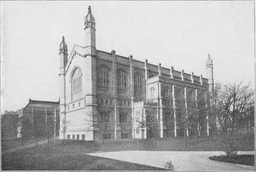
THE BUILDING OF THE LAW SCHOOL OF THE UNIVERSITY OF CHICAGO.
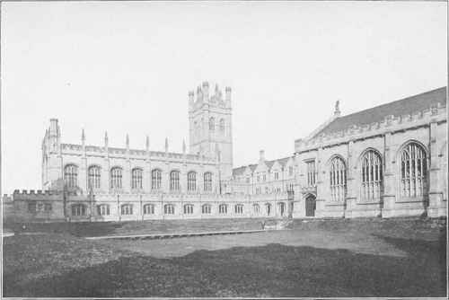
TOWER GROUP AT THE UNIVERSITY OF CHICAGO.
Shepley, Rutan & Coolidge, Architects, Chicago, 111.
On the Right is the LeonMandel Hall; Adjoining this is the Reynolds Club-House, with the Founder's Tower; on the Left is Hutchinson Hall.
Group Completed in 1902. Other University Buildings Shown on Page 187.
Next place arrowheads on ab and ad at joints (1) and (1) to represent a push and a pull respectively. There remains now but one stress undetermined, that in of. It can be ascertained by drawing the polygon for joint 1 or 1; let us draw the latter. There are four forces acting at that joint, namely, the 600-pound load, and the forces exerted by members ed, da, and af. The first three forces are already represented in the drawing by EF, DE and DA, and the polygon for those three forces (not closed) is ADEF. The fourth force must close the polygon, that is, a line from F parallel to of must pass through A, and if the drawing has been accurately done, it will pass through A. The polygon for the four forces then is ADEFA, and an arrowhead placed on FA ought to point to the left, but as before, place it in the truss diagram on af near joint (1). The force exerted by member of on joint (1) being a pull, of is under tension, and since AF measures 1.12 inches, the value of the tension is 1,120 pounds.
Since of is in tension it pulls on joint (1), hence we place an arrowhead on of near joint (1) to indicate that pull.
Examples For Practice
1. Construct a stress diagram for the truss of the preceding Example (Fig. 22a) making all the polygons counter-clockwise, and compare with the stress diagram in Fig. 22.
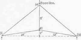
Fig. 23.
2. Determine the stresses in the members of the truss represented in Fig. 23 due to a single load of 2,000 pounds at the peak.
Ans. | Stresses in |
Stresses in | |
Stress in 24 = 490 pounds. |
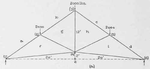
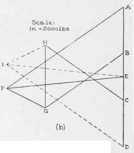
Fig. 24.
27. Stress Records. When making a record of the values of the stresses as determined in i an analysis of a truss, it is convenient to distinguish be-tween tension and compression by means of the signs plus and minus. Custom differs as to use of the signs for this purpose, but we shall use plus for tension and minus for compression. Thus + 4,500 means a tensile stress of 4,560 pounds, and - 7,500 means a compressive stress of 7,500 pounds.
The record of the stresses as obtained in an analysis can be conveniently made in the form of a table, as in Example 1 following, or in the truss diagram itself, as in Example 2 (Fig. 25).
As previously explained, the stress in a member is tensile or compressive according as the member pulls or pushes on the joints between which it extends. If the arrowheads are placed on the lines representing the members as was explained in Example 1 of Art. 26 (Fig. 22), the two arrowheads on any member point toward each other on tension members, and from each other on compression members.
If the system of lettering explained in Art. 24 is followed in the analysis of a truss, and if the first polygon (for the loads and reactions) is drawn according to directions (Art. 26), then the system of lettering will guide one in drawing the polygons for the joints as shown in the following illustrations. It must be remembered always that any two parallel lines, one in the truss and one in the stress diagram, must be designated by the same two letters, the first by small letters on opposite sides of it, and the second by the same capitals at its ends.
Continue to:
My Books

