Mill Building. Part 5
Description
This section is from the book "Cyclopedia Of Architecture, Carpentry, And Building", by James C. et al. Also available from Amazon: Cyclopedia Of Architecture, Carpentry And Building.
Mill Building. Part 5
Fig. 114. Position of Crane Truck for Maximum Reaction on Column.
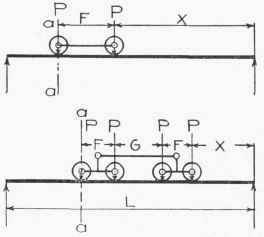
Fig. 115. Position of Crane Truck for Maximum Shear at any Section.
The maximum shear in the runway girder will occur when the crane wheels are in the position shown in Fig. 112; and the maximum moment will occur under the wheel nearest the middle of the span, when the wheels are in the position shown in Fig. 113. The maximum reaction of the runway girders on the column will occur when the wheels are in the position shown in Fig. 114. In order to
Table XIV. Maximum Crane Reaction
Capacity (tons) | Span (feet | A | B | c | D | E | F | G | Wheel Load (in lbs.) | Tram Rail Am. Std. | H | ||||||||
in. | ft. | in. | ft. | in. | ft. in. | ft. | in. | ft. | in. | ft in | ft. in. | ||||||||
SINGLE DRUM. TYPE C | 40 | 7 | 4- | 5½ | 1- | 8 | 7 | 7- | 64 | 10 000 | 34- | 1⅞- | 40 | 1- | 5 | ||||
2- | 0 | ||||||||||||||||||
5 | 60 | 8 | 4- | 74 | 1_ | 11 | 5 | 9- | 0 | 12 500 | |||||||||
1 2- | 1 | ||||||||||||||||||
80 | 8 | 4- | 8½ | 1- | 11 | 4 | 9- | 34 | 15 500 | ||||||||||
2- | 2 | ||||||||||||||||||
40 | 8 | 5- | 0½ | l- | 0 | 9 | 8- | 54 | 16 500 | 34- | 1⅞- | 40 | 1- | 0 | |||||
2- | 4 | ||||||||||||||||||
10 | 60 | 8 | 4- | 11½ | f 1- | 11½ | 10 | 9- | 7¼ | 19 500 | |||||||||
1 2- | 4 | ||||||||||||||||||
80 | 8 | 5- | 0½ | 1- | 11½ | 9 | 9- | 94 | 23 000 | ||||||||||
2- | 4½ | ||||||||||||||||||
40 | 8 | 5- | 4¼ | 5 2- | 0 | 1-34 • | 2- | 0 | 9- | 6 | 24 500 | 3⅞ | 2⅛- -8 | 50 | 1- | 3 | |||
2- | 9 | ||||||||||||||||||
15 | 60 | 8 | 5- | 4¼ | 2- | 0 | 1-34 | 2_ | 0 | 10- | 74 | 28 000 | |||||||
2- | 9 | ||||||||||||||||||
80 | 8 | 5- | 5½ | 2- | 0 | 2¼ | 2_ | 0 | 10- | 94 | 31 500 | ||||||||
2- | 9 | ||||||||||||||||||
40 | 8 | 5- | 54 | 2- | 0 | 1-6¼ | 2- | 0 | 9- | 6 | 30 000 | 3 | 2⅛- | 50 | 1- | 3 | |||
2- | 9 | ||||||||||||||||||
20 | 60 | 8 | 5- | 5½ | 2- | 0 | 1-6¼ | 2_ | 0 | 10 | 74 | 34 000 | |||||||
2- | 9 | ||||||||||||||||||
80 | 9 | 5- | 6½ | 2- | 0⅛ | 1-5¼ | 2_ | 0 | 11- | 14 | 38 000 | ⅞- | |||||||
2- | 9 | ||||||||||||||||||
DOUBLE DRUM. TYPE A | 40 | 9 | 6- | 0¼ | 2_ | 6 | 3-9¼ 2- | 74 | 11- | 0½ | 38 600 | 4¼- | -8 | 60 | 1- | 3 | |||
25 | 60 | 9 | 6- | 0½ | 2- | 6 | 3-9! | 2- | 74 | 11- | 3½ | 42 400 | |||||||
80 | 10 | 6- | 2¼ | 2- | 6 | 3-7! | 2- | 74 | 11- | 84 | 47 000 | ||||||||
40 | 10 | 6- | 3¾ | 2- | 7 | 3-8½ | 2- | 10 | 11- | 44 | 45 600 | 4i- | 2|- | 60 | 1- | 3 | |||
30 | 60 | 10 | 6- | 3¾ | 2- | 7 | 3-84 | 2- | 10 | 11- | 64 | 49 600 | |||||||
80 | 10 | 6- | 3f | 2- | 7 | 3-8½ | 2 | 10 | 12- | 0 | 54 600 | ||||||||
40 | 11 | 7- | 4½ | 3- | 1½ | 4-24 | 3- | 84 | 12- | 8 | 59 600 | 5 - | 24- | 80 | 1- | 6 | |||
40 | 60 | 11 | 7- | 4½ | 3- | 1½ | 4-24 | 3- | 8½ | 13- | 0 | 64 000 | |||||||
SO | 11 | 7- | 4½ | 3- | 1½ | 4-24 | 3- | 84 | 13- | 5 | 70 000 | ||||||||
40 | 13 | 7- | 11½ | 3- | 6 | 4-04 | 3- | 9 | 13- | 10½ | 77 000 | 5f- | 2¾- | LOO | 1- | 6 | |||
50 | 60 | 13 | 7- | 11| | 3- | 6 | 4-0½ | 3- | 9 | 13- | 10½ | 84 600 | |||||||
80 | 13 | 7- | 114 | 3- | 6 | 4-04 | 3- | 9 | 14- | 0 | 92 000 | ||||||||
40 | 14 | 8- | 7¼ | 4- | 1 | 4-3¾ | 4- | 44 | 15- | 2 | 88 000 | 5i- | 2¾-] | [00 | 1- | 11 | |||
60 | 60 | 14 | 8- | 7¼ | 4- | 1 | 4-3f | 4- | 4½ | 15- | 2 | 94 000 | |||||||
80 | 14 | 8- | 7i | 4- | 1 | 4-3f | 4- | 44 | 15- | 4 | 103 000 | ||||||||
40 | 12½ | 10- | 3¼ | 4- | 0 | 2-7¾ | 4- | 4½ | 3- | 6 | 5-4 | 44 000 | 5¾- | 2¾-l | 00 | ||||
60 | 60 | 12½ | 10- | 3¼ | 4- | 0 | 2-7¾ | 4- | 4½ | 3- | 6 | 5-4 | 47 000 | 6 - | 4 -1 | 50 | |||
80 | 12½ | 10- | 3¼ | 4- | 0 | 2-7¾ | 4- | 44 | 3- | 6 | 5-4 | 51 500 | |||||||
40 | 12½ | 11- | 3 | 4- | 6 | 3-8½ | 4- | 0½ | 5- | 0 | 6-0 | 55 000 | 5¾- | 2¾-l | 00 | 2_ | 2 | ||
75 | 60 | 12½ | 11- | 3 | 4- | 6 | 3-84 | 4- | 04 | 5- | 0 | 6-0 | 60 000 6- | 4 -1 | 50 | ||||
80 | 12½ | 11- | 3 | 4- | 6 | 3-84 | 4- | 04 | 5- | 0 | 6-0 | 64 000 | |||||||
40 | 16½ | 13- | 2¼ | 4- | 1 | 2-0 | SPECIAL | 5- | 0 | 6-0 | 83 000 | 6 - | 4 -1 | 50 | 4- | 7 | |||
100 | 60 | 164 | 13- | 2¼ | 4- | 1 | 2-0 | " | 5- | 0 | 6-0 | 86 000 | |||||||
80 | 16½ | 13- | 2¼ | 4- | 1 | 2-0 | " | 5- | 0 | 6-0 | 89 000 | ||||||||
40 | 17 | 15- | 6⅛ | 6- | 0 | 3-2 | " | 6- | 0 | 6-0 | 130 000 | 6 - | 4 -1 | 50 | 4- | 7 | |||
150 | 60 | 17 | 15- | 6⅛ | 6- | 0 | 3-2 | " | 6- | 0 | 6-0 | 134 000 | |||||||
80 | 17 | 15- | 6⅛ | 6- | 0 | 3-2 | " | 6- | 0 | 6-0 | 139 000 | ||||||||
Table XV. Typical Electric Cranes
Capacity (Tons) | Span (Ft.) | Wheel Base F | Wheel Load P | A+2 in. | B | Weight of Runway Rail | ||
For Plate-Girders | I-Beams | |||||||
5 | 40 | 8 ft. | 6 in. | 1 2 000 | 10 in. | 7 ft. | 40 lbs. per yd. | 40 lbs. |
60 | 9" | 0 " | 13 000 | 10 " | 7 " | 40 " | 40 " | |
10 | 40 | 9 " | 0 " | 19 000 | 10 " | 7 " | 45 ' | 40 " |
60 | 9 " | 6 " | 21 000 | 10 " | 7 " | 45 ' | 40 " | |
15 | 40 | 9 " | 6 " | 26 000 | 10 " | 7 " | 50 ' | 50 " |
60 | 10 " | 0 " | 29 000 | 10 " | 7 " | 50 ' | 50 " | |
20 | 40 | 10 " | 0 " | 33 000 | 12 " | 8" | 55 ' | 50 " |
60 | 10 " | 6 " | 36 000 | 12 " | 8 " | 55 ' | 50 " | |
25 | 40 | 10 " | 0 " | 40 000 | 12 " | 8 " | 60 ' | 50 " |
60 | 10 " | 6 " | 44 000 | 12 " | 8 ': | 60 ' | 50 " | |
30 | 40 | 10 " | 6 " | 48 000 | 12 " | 8 " | 70 ' | 60 " |
60 | 11" | o " | 52 000 | 12 " | 8 " | 70 ' | 60 " | |
40 | 40 | 11 " | 0 " | 64 000 | 14 " | 9 " | 80 ' | 60 " |
60 | 12 " | 0 " | 70 000 | 14 " | 9 " | 80 ' | 60 " | |
50 | 40 | 11 " | 0 " | 72 000 | 14 " | 9 " | 100 ' | 60 " |
60 | 12 " | 0 " | 8O 000 | 14 " | 9 " | 100 ' | 60 " | |
obtain the maximum shear at any section, as a-a, the load should be placed as shown in Fig. 115: and the maximum shear will then be the left reaction, which is R = 2 P (x + F/2 ) ÷ l, for two wheels: and R = 4 P (.x + F + G/2) ÷ l, for four wheels.
The values of P for traveling cranes of various capacities and spans may be obtained upon writing to the various crane manufacturing companies, whose addresses will be found in the advertising sections of the engineering periodicals. The distances between wheels may be obtained from their catalogues, which may be had upon application. The values of P, and the distances between wheels for cranes of various spans and capacities, are given in Table XIV, which is made from information furnished through the courtesy of Pawling & Harnischfeger, Milwaukee, Wisconsin.
The values in Table XV are taken from the "Transactions" of the American Society of Civil Engineers, Vol. 54, p. 400, 1905. They are for typical traveling electric cranes, and are proposed by Mr. C. C. Schneider, one of the most distinguished of structural engineers.
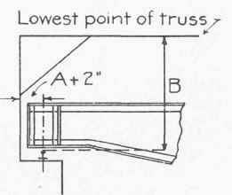
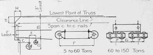
Fig. 116. Showing Notation used in Table, XV.
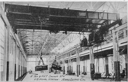
Fig. 117. Five-Ton Electric Traveling Cranes Installed at TJ. S. Naval Station, Mare Island, California, Courtesy of Cleveland Crane & Car Company, Cleveland, Ohio.
The side clearance B from the center of the rail, and the vertical clearance of the beam from the top of the rail, are given in this table (see Fig. 116). These values for the cranes of different manufacturers may be obtained from their catalogues; and they must be known, in order that the crane shall not interfere with the columns or the roof trusses.
If the runway girder is composed of an I-beam, a channel is usually riveted to its top; and on this the rail on which the crane wheels move is fastened down at intervals (see Fig. 107) of about 2½ or 3 feet. Figs. 106 and 117 show details of this kind of girder. Note that the rails are U-shaped (see Fig. 105). This rail is used extensively, although in many cases the common T-rail is used and is fastened down by means of clamps around the edge of the flange of the girder (see Fig. 110).
In case plate-girders are necessary for runway girders, they must be designed. The depth of these girders should be 1/10 to 1/6 of the distance between trusses or columns - that is, 1/10 of their span; The depths must be in the even inch. For example, if the trusses were 16 feet apart, the depth of the girder would be 16 ÷ 10 = 1.6 feet, which is equal to 19.2 inches. The depth of the girder must then be made 20 inches, since, if it were made 19 inches, it would be'difficult to obtain a web plate 19 inches wide, for the mills do not as a rule have plates of odd-inch widths in stock.
The thickness of the web plate is given by the formula: t= va/S5d; but in no case shall it be less than 5/16 inch. In this formula, V0 is the maximum end reaction of the runway girder. It is equal to R as given by the formula on p. 87, when x is equal to l - F, and d is the depth of the girder, which is equal to the depth of the web plate, and Ss is the unit allowable shearing stress.
The flanges are composed of two angles, placed with the long legs horizontal in case unequal-legged angles are used. The required net area of one flange is given by the formula:
A=Mm/S2 (d-2)' in which Mm is the moment obtained when the wheels are in the position shown in Fig. 113, St is the unit allowable tensile stress, and d is the width of the web plate. If the area A has been computed, two angles must be found from the tables in the Carnegie Handbook, such that when one ⅞ -inch or ¾-inch rivet-hole, as the case may be, is taken out, each angle will give a net area equal to or slightly in excess of the area A. These flange angles must be riveted to the web by rivets placed a certain distance apart. For convenience of manufacture, the girder is divided into ten equal parts, and the rivet spacing between any two of these divisions-or tenth-points, as they are called - is kept the same. These tenth-points are numbered (see Fig. 118). The rivet spacing in the first division is the same as that computed for the end of the girder, which is the zero tenth-point; the rivet spacing in the second division is the same as that computed for the 1st tenth-point; and so on. The rivet spacing at any point is given by the formula:
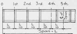
Fig. 118. Position of Tenth-Points.
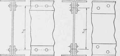
Fig. 119. Determination of Distance between Gauge Lines.
in which,
Vx = Maximum shear at the point; v = Maximum allowable stress on one rivet; this will be the bearing value of the rivet in the web plate (see Table X, p. 47); P = Maximum reaction of one crane wheel (see Table XIV or XV); hg = Distance between gauge lines of the angles.
Continue to:
My Books

