Structural Drafting Part I. Drafting Room Equipment And Practice. Part 2
Description
This section is from the book "Cyclopedia Of Architecture, Carpentry, And Building", by James C. et al. Also available from Amazon: Cyclopedia Of Architecture, Carpentry And Building.
Structural Drafting Part I. Drafting Room Equipment And Practice. Part 2
Great care should be taken in making the changes that no dimensions or other notations written upon the drawing by the checker are rubbed off. The checker then examines the drawing carefully to see that all the errors which he has pointed out have been corrected. He then cleans the tracing, signs his name to it, and returns it to the squad boss. The squad boss in turn has the necessary blue prints made and turns the tracing together with the prints over to the chief draftsman, who in turn files the tracing in its proper place and gives the blue prints to the engineer of the plant who sees that they are distributed to the foremen of the various shops where they are required.
Records. A job is known by the order number which is given it when it comes into the hands of the engineer of the plant. This order number should go on all papers upon which anything concerning that structure is placed. Failure to do this will result in great confusion and much time will be lost. The penalty for persistent failure to comply with this very important method of procedure is usually dismissal.
Since the draftsman, or in fact any of the office force, may work upon more than one order during the day or week, and since it is important that the cost of the drafting or engineering work for any particular order should be known, it is essential that the men keep time cards upon which the order and the time placed upon that order is noted. Usually fractions of an hour less than one-fourth are not reported. Fig. 1 shows one of these time cards upon which is noted the work of a checker for one week. It shows that he has worked upon several orders and also shows the exact amount of time he has placed upon each one and also the rate per hour which he received. In this way it is possible to obtain the cost of engineering of any particular order when it has finally been finished.
An orderly record of the passage of the work from the time the stress sheet enters the engineer's office until the material has been shipped, and also a record of the progress of the work during erection, should be kept. This is usually kept on 3x5 cards in the engineer's office. In addition to this card-index record, a monthly report in blue print form is kept showing the progress of the various orders. For instance, the progress report would contain such items as these: Order received, layouts made, material ordered, detailed sheets
FORM 0 & E I53-20M-I0-22-23 ENGINEERING DEPARTMENT | |||||||||||||||||
NAME...J.A.Frost.......... | RATE 60 | ||||||||||||||||
TIME CARD FOR WEEK ENDING. .August..13..1904. | |||||||||||||||||
ORDER Number | Div. | Sun. | Mon. | Tue. | Wed. | Thur. | Fri. | Sat. | Sun. | Mon. | Tue. | Wed. | Thur. | Fri. | Sat. | TOTAL HOURS | COST |
B412c | 6 | 4 | 5 1/2 | 4 | 6 | 25 1/2 | |||||||||||
B413C | 5 1/2 | 4 1/2 | 6 | 4 | 5 1/2 | 25 1/2 | |||||||||||
Estimating | |||||||||||||||||
General | |||||||||||||||||
Holiday | |||||||||||||||||
Total | 11 1/2 | 8 1/2 | 11 1/2 | 8 | 11 1/2 | 51 | |||||||||||
Sick | 4 | 4 | |||||||||||||||
Vacation | |||||||||||||||||
Out | |||||||||||||||||
Total | 11 1/2 | 8 1/2 | 11 1/2 | 8 | 11 1/2 | 4 | 55 | ||||||||||
HOURS WORKED | ... | 51 | |||||||||||||||
,, | ALLOWED (not worked) | ||||||||||||||||
,, | PAID FOR..... | 51 |
| ||||||||||||||
Fig. 1. Draftsman's Time Card Showing Hours Spent on Order Indicated finished, shop bills made, templet work finished, work fabricated, work shipped; and in addition to this progress report, which is made cut in the office, is the report of the erector on a job in the field. The erector's form of report contains such headings as tend to indicate the progress in the false work; the erection of the trusses and floor system; and the amount of field riveting and painting completed.

Fig. 2. Side View of Drawing Board, Having Elevating Peg3.
Drafting Materials. Instruments. The drafting instruments required are: A drawing board, T-square, triangles of various kinds as noted below, pencils, scales, erasers and erasing shields, a set of drawing instruments, a large linen cover, and half sleeves.
The drawing board should be made of soft pine with battens upon the back in order to prevent the warping of the board. Since few drawings in structural engineering are larger than 24x 36 inches, it is not necessary to have the drafting board larger than 26X38
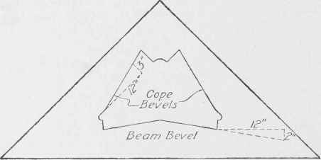
Fig. 3. 45° Triangle with Cope and Beam Bevels.
inches. A drafting board should not lie close to a table, but should be raised from the table by small legs placed at its upper edge as indicated in Fig. 2.
The T-square should be about 40 inches in length and should be of good quality with an amber edge upon each side. The amber edge is of great advantage since it will allow the draftsman to see lines below that one which he is drawing and, therefore, prevent him from overrunning by drawing one line past its limiting point. Such a T-square may be procured for about $2.25.
The triangles should be of amber or celluloid, and should consist of the following: One 45-degree triangle with 10- or 12-inch sides; one smaller, say with 6-inch sides; two 60-degree triangles with 10-inch sides; and two with 4-inch sides. One or more of these triangles should have the beam and coping bevels fixed upon it as in Fig. 3; this will have to be done by the draftsman, since no such triangles are on the market.
The pencils used by the draftsman should be such as will make clear and black lines upon paper in case the drawing is to be traced. If the drawing is not to be traced, a harder pencil will suffice. In case a drawing is made directly upon tracing cloth, a soft pencil should be used and it should be kept sharpened. This will necessitate frequent rubbing over the sand paper pad which every draftsman should have close at hand in order to keep a good point upon his pencil. The pencil recommended for detailing where a tracing is to be made is "Koh-I-Noor, 3H," although some draftsmen prefer 4 H or 5 H. The latter are, in the writer's opinion, to be recommended for detailing where a tracing is not required from the original. In case drafting is done directly upon tracing cloth, a 2 H pencil is the correct one to use.
A red pencil should be kept for marking upon blue prints and a blue pencil for making checks on tracings. Never use a red pencil upon tracing cloth, since it will not be easy to erase, whereas the blue-pencil mark may be washed off with gasoline or erased with a pencil eraser.
The scales required are the architect's and the engineer's. The former has certain divisions upon it and each of these divisions is divided into twelve parts which indicate inches, and these parts are in turn divided into halves or quarters or other small divisions denoting the fraction of the inch. The architect's scale which best serves the purpose is the one which has the 2-inch, 1 1/2-inch, 1-inch 1/2-inch, 3/4-inch, 3/8-inch, 1/4-inch, 1/8-inch, 3/16-inch, and 3/32-inch scale. A special scale for the making of drawings to a large size or for the making of layouts is a great convenience. Such a scale is on the market and is divided so that half of an inch is equal to one inch. This scale should be in the outfit of all checkers. The engineer's scale is one on which the inches are divided into certain decimal divisions. The best scale for this is that which has its edges divided into 10, 20, 40, 50, and 00 parts of an inch. This scale is of use only in laying off bevels and natural functions of angles or in drawing outlines upon which details will be constructed with the use of the architect's scales. The tendency of young engineers to use the engineer's scale, allowing a certain decimal to equal a certain fraction of an inch, is to be discouraged because of the liability of error, and a severe penalty imposed for a second offense. Care should be taken in the use of scales such as the architect's which have different scales on the same edge in order not to get the feet which belong to the wrong scale.
Continue to:
My Books

