Chapter XI. Domes
Description
This section is from the book "Modern Buildings, Their Planning, Construction And Equipment Vol5", by G. A. T. Middleton. Also available from Amazon: Modern Buildings.
Chapter XI. Domes
(Contributed by Walter Hooker)
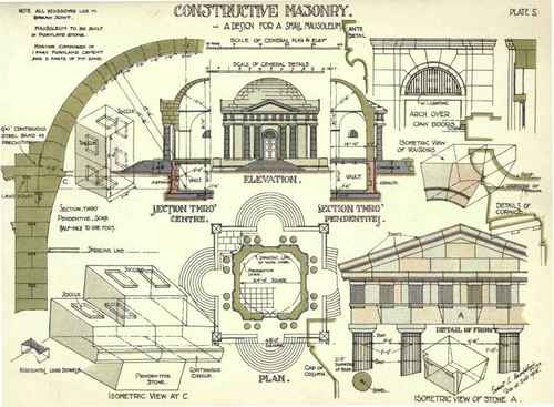
The full-page drawing, Plate V., gives the general drawings with constructional details of a small Mausoleum in stone, designed by Mr. E. L. Hampshire, A.R.I.B.A.
The general scheme will be seen to embrace a severe Classic chamber, with a vault below, and porticoes on each of the four facades, approached by flights of steps in concentric semicircles.
The main principles involve the application of a domical roof over a four-sided chamber, with the angles curtailed by splays with salient rings over, forming pendentives.
The chamber measures 24 feet square from the main walls, and the diameter of the dome is of the same dimension.
The walls are necessarily of massive design, to resist the thrust of the heavy masonry in the dome. These are further strengthened by the porticoes, and the stability is increased by the weight of the pediments on each facade.
The inner curve of the dome is struck from a centre on a line with the under side of the cornice, and in section is a semicircle.
The weight of the dome is minimised and economy studied by reducing the thickness of the dome at the apex and increasing it at the haunches and springing line.
The centre for the outer arc of the dome is found, therefore, somewhat below that of the inner or intradosal arc.
The setting out for the stones of the vertical walls, columns, and their entasis, pediments, etc. needs no further comment, as general details of the method usually employed are given elsewhere in this volume.
The pendentives and dome, however, require more particular attention.
It will be seen that the pendentives are generated from a plane surface oversailing in a curve vertically to meet the periphery of the dome.
To set out the stones - lay out on a plane surface or even floor the plan of the wall at the springing line of the pendentive, which is a right angle formed by the two main walls, having the entering angle splayed at an angle of 135 degrees with each face, as shown in Fig. 126.
From C, the centre of the circumference of the dome at the springing line, and at 12 feet distance from the wall faces, draw a circle tangentially to the same. This will give the projection of the pendentive.
The vertical curve is found by setting out the projection from the wall face and the height at any convenient point, and proceeding in the usual way when a centre is to be found, i.e. by means of arcs dividing the chords. A line drawn through the points of contact of the arcs will contain the centre of the curve of the pendentive. This also is shown in Fig. 126.
In setting out the joints, which are shown in Fig. 126 asplane surfaces and not as joggles as in Plate V., each should be struck to the radius of the circle on plan, while the beds are commonly set out horizontally, though it is permissible to radiate them from the centre of the vertical curve.
All stones should break-joint. Any one stone can now be set out by a reference to the plan and section. (Fig. 126). An isometric view of stone A on plan is shown in Fig. 126.
The method of bringing the stone to the finished shape has already been described.
The particular bevels required in this instance are obtained by reference to the plan, and additional bevels are taken from the arcs of the pendentive, both horizontal and vertical. There is one feature worthy of note respecting the obtuse angle at the base of the stone dying into the curves of the upper portion. The joggles present no difficulty, provided that care be taken to allow sufficient stone for the salient joggle when sawing out of the rough.
A similar system is applied to the setting out the stones of the dome. As these all have radiating beds and joints, one set of bevels will apply to nearly all the stones.
It may be noted that, as the horizontal and vertical beds and joints are in neither case square with the axis of the stones, the bevels will have to be made accordingly. This is illustrated in Fig. 127, showing the axial line of one of the stones, with the dotted lines representing the enclosing squared block. These stones can be prepared in pairs, the saw cut dividing them being utilised to form a bed or joint, as may be convenient, and thus save time and labour(see Fig. 128).
Isometric views are shown on Plate V. of various stones, with the method of joining and details of the application of secret joints and of the cornice mould, which are sufficiently explanatory of themselves to need no further comment.
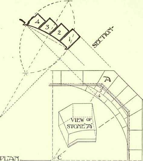
Fig. 126.
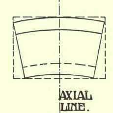
Fig. 127.
Figs. 129, 130, and 131 give the plans, section, and elevation of the central tower for a new dyehouse designed by Mr. A. W. S. Cross, F.R.I.B.A.
The plan is laid out on the basis of an octagon, with buttresses at the salient angles skilfully masked as columns supporting the well-proportioned cornice.
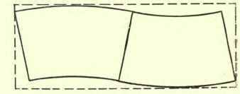
Fig. 128.
The lower portion is entirely of stone externally with brick backing.
Access is given to the main entrance by a flight of four broad steps of semicircular shape on plan, thelowest of which is carried well outwards, the end cutting into the base with a flat sweep.
The pedestals of the columns are carried on a plinth mould at the floor line, the main portion being of ashlar with recessed joints running continuously between the pedestals and forming a regular base to the building.
The upper part of the pedestals is finished with a cornice mould of regular design, on which the bases of the columns rest.
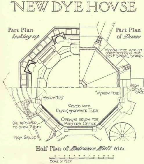
Fig. 129.
The columns are of rounded section on the face, their backs being jointed with the brickwork of the main wall, and their lower portion interrupted with alternate squared stones and completed with a cap and neck mould. Over these a heavy entablature is supported, with architrave, frieze, and cornice, finished with a blocking course.
The whole is completed by an octagonal domed roof, composed of two curves of contrary flexure, with a horizontal band at the junction, the angles abutting on the blocking course being finished with moulded consoles. The apex stone is surmounted by a moulded base carrying an ornamental metal finial.
The entrance is recessed between the pedestals of the front elevation, with a flat arch in one stone moulded on the edge and carrying a projecting transome over, which also forms a sill for the window and constitutes a horizontal band with the adjacent walls. Light is provided by semicircular openings with alternate arch stones and brickwork, the stone voussoirs being salient.
Circular bullseye lights or lunettes are provided with moulded arch stones and keys at right angles to each other.
Respecting the individual portions of the stonework, such as the doors, windows, columns, entablature, etc., sufficient detailed descriptions have been provided in other chapters for no further reference here to be needed. As regards the dome itself, this presents distinctive features which require some more precise description.
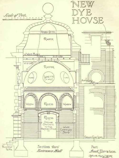
Fig. 130.
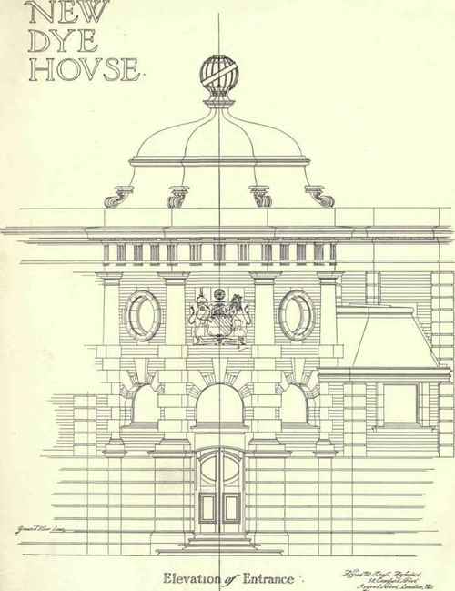
Fig. 131.
It will be seen that the lower half is shown with the joints horizontal, and that advantage has been taken of the design to give increased stability to the whole by widening the beds of the lower courses. It might be considered advisable to joggle one or two of the lowest of these, although, as the superincumbent weight is not excessive, this has not been considered absolutely necessary. On this lower section a complete course or band of terra-cotta has been inserted, which acts as a stop to the plaster face of the interior, and also, from the length of the pieces, would to some extent act as a tie to the structure.
Above this the voussoirs have been joggled to guard against opening out of any of the courses.
The method of setting out any individual stone has already been explained.
Stones have been inserted in the face of the wall over the main entrance with a carved coat of arms thereon. These are bosted out and left with sufficient projection to be finished by the carver when the building is nearing completion.
Continue to:
My Books

