Pointed Or Gothic Vaults. Continued
Description
This section is from the book "Modern Buildings, Their Planning, Construction And Equipment Vol5", by G. A. T. Middleton. Also available from Amazon: Modern Buildings.
Pointed Or Gothic Vaults. Continued
The position of the curve of each rib is found and marked on the stone, and templates cut to the curve are applied to the nosing of the stones to which the faces are worked. The mouldings are then cut into the marks on the top and bottom beds.
The intermediate stones present no difficulty, as they are simple sections of each rib with the beds cut to bevels radiating from the several centres of the arcs or curves (as the case may be) from which the ribs spring. The backs of the stones are rebated to form a key for the panelling or vaulting surface between the ribs.
The keystones usually require somewhat different treatment, as the junction of the ribs being on different planes the mouldings do not mitre correctly. It is usual in this case to form the keystone as a boss or carved projection, and to let the ribs disappear behind the carving.
In the present instance, as the ribs intersect at right angles, mitres could be applied with propriety, a plan of the key being shown (see Fig. 123) together with an elevation giving the bevel of the joints and the face of one of the joints with the moulding of the rib in section. The dotted lines indicate the outline of the squared stone before the operation of cutting is proceeded with. The face of the joints would be worked first by means of proper bevels raking from the squared surface of operation.
In all cases the joints are worked to a plane surface first, and to the true rake; and on each joint the section of the moulds is punched in on the faces thus formed by the aid of zinc templates accurately cut to shape.
The stone is then worked to the mouldings back towards their intersection or mitre line, and the raking bevels are applied to give the curve to the face of the moulds. The top of the stone can follow the same bevel or may be left square, the rebates as shown being used to key the panel stones.
In the case of the panels, the work is built in regular courses at right angles to a line bisecting the angle formed by two adjacent ribs on plan. The surface is slightly concave, thus forming a flat arch. Where two of these vaulting surfaces unite, the stones along the groin line are formed as shown in the section of rib in Fig. 123, in order to bond with the coursing. In this case no rib is projected on the groin line. The joints of the panelling frequently present a twist when seen from below. This is termed "ploughshare" coursing, from its fancied resemblance to that implement, and is employed to render the thrust on the panel units even and within the limits of stability.
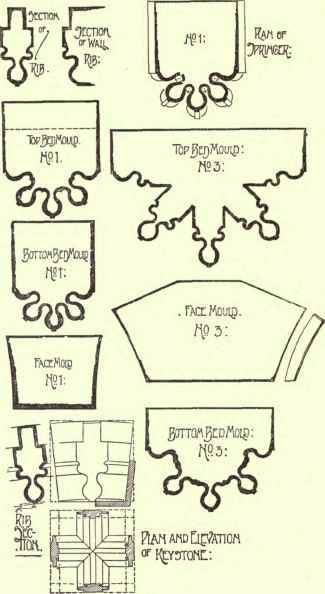
Fig. 123.
Reference has been made to cases wherein ribs, not meeting at the apex at right angles (such as in cases where the vaulting surfaces are not square but oblong) the intersection of the mouldings would not form true mitres. In these cases the defect, as just said, is hidden by employing carved bosses, projecting from the keystones in such a manner as to absorb the mouldings, which die into the carvings without contact with each other.
To set the keystone out with its boss proceed as follows.
Lay out a template with one edge square and the other laid off to the curve of the diagonal ribs. From the square edge lay off a line perpendicular to it, forming the axis of intersection of the various ribs. Set out similar templates, with the curves of the other ribs forming the junction at the key, and with square edges as before; and lay off adjacent to the perpendicular line the portion of the boss that would be required to cover the mitre were it to be carried through. Cut away the stone to the curve of the template for the main rib, and proceed with the intermediates by applying their several templates at their true angles with the surface thus formed, and cutting down until the faces are out of winding. The surfaces will then show the curves of the ribs on the soffit, the stone for the boss carving being left for the final operation. The remaining part of the work is proceeded with similarly to that described for the ordinary rib stones. The joints will, of course, be formed at right angles to the curve of the ribs with which they are designed to engage.
Plate IV. the work of Mr. John Ormrod, A.R.I.B.A., shows the plan, sections, and setting out, together with details of a continuous groined vault of more elaborate design than the one previously detailed.
In this case it will be seen that ridge ribs and intermediates are introduced in addition to the transverse and diagonal ribs. Another feature may be noticed in that the height of the wall ribs is lower than the diagonals and transversals. This admits of a certain amount of rise in the ridge rib connecting the apices of the wall and the diagonal ribs, and may be considered as adding both to the beauty and stability of the general vaulting.
An enlarged plan of the ribs at their junction on the springing line, together with outlines of the mouldings at different levels, serves to show the gradual clearance of the members of the mouldings on the ribs, until, at EE, their final severance each from the other is completed and the panelling between them emerges from the mouldings.
The sections of the rib faces are clearly shown by the dotted lines over the plan, with the points of departure from the springing line and the centres from which they are struck.
The wall ribs in this instance are stilted. As the transverse ribs more frequently govern the general characteristics of the structure in this type of vaulting it is usual to set these out first. The height of the vault being fixed, the ribs may be struck either as one or two centred arcs. In this instance it is one centred, but with the centre well beyond the half of the span, to give a well pointed arch.
The next point is to settle the diagonals. The radius should be as nearly as possible similar to that of the transverse and the centres on the springing line of the vaulting. The vertical height being set out by drawing a perpendicular to the centre of the diagonal on plan, and marking off the vertical height of the transverse ribs, an arc with the centre of the boss and distance equal to the height will give the curve of the diagonal. The intermediates are obtained by a similar method as respects those engaging the longitudinal ridge. The cross ridges (from the apex of the wall ribs to the boss at the junction of the diagonals) are curved, and are governed by the difference in the height of the apex of the wall ribs and that of the junction of the diagonals were they allowed to meet (presuming the boss to be removed). This is set out in cross section, and a centre found that will give a flat cambered arch suitable to the difference of vertical height between the two points.
The intermediate rib VV can be set out from this as respects its height, as the position of the point of junction between this and the cross ridges at the centre of the boss is shown in the curve of the cross ridge already laid down, and its springing line is common to the other ribs.
It should be further borne in mind that, with reference to the primary ribs more especially, but also with all the ribs, it is necessary that the separation of the members of the mouldings and of the disengagement of the ribs as a whole should be effected as nearly as possible at a uniform level. To effect this, commencement may be in this instance made with the transverse rib, which presents no difficulty, as a simple segment of a circle suffices to define its outline. The diagonals, however, should be set out as far as the line of severance of the ribs on plan by a vertical line, such as Ea or Eb, as shown on Fig. 122, the joint being shown here as a radiation from the centre of the curve forming the soffit line of the transverse rib. The projection is therefore a fixed dimension up to this joint for all the ribs.
It will be seen by a reference to the plan that the diagonal has a greater projection from springing to apex than the transverse rib. It results therefore that an arc will have to be found that will be tangential to that from the springing to the joint face, and that will touch the apex height at the point of contact of the diagonals.
This can be done by means of the methods set out in Chapter VI (The Geometry Of Masonry).
The system of arranging the joints and the moulds and templates required for the various stones has already been described.
The bosses, however, merit a further description. Take, for example, the centre boss, which forms the junction of the diagonals and ridge ribs, and is therefore a stone having 8 joints or stumps to engage with the 4 diagonals and 4 ends of the ridge ribs.
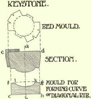
Fig. 124.
The bed mould is simply a replica of the stone on the plan, with the adjoining stone work removed, as shown in Fig. 124.
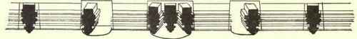
Fig. 125. Elevation Of Transverse Rib.
The sections are more complicated, and it is better to arrange the joints in such a manner that those of the diagonals are struck from the respective centres of the curves of the ribs. The ridges are better cut in reverse, and either rebate jointed or made to form skewbacks for the adjacent stones of the ridge ribs, as shown in Fig. 125 and in Plate IV. By this means additional stability is given to the apex stone. A section through the diagonals, and giving the radiating joints, appears in Fig. 124.
The bevels are applied from the surface of operation, as cd, which is at right angles to ab, the centre of the stone and the axis thereof. The moulds are used only to obtain the curves of the ribs, as their direct application is not practicable.
The bed mould is scribed on the surface cd, and the direction of the ribs from the common centre thus accurately gauged.
The radiating joints of the diagonals are next ascertained, and the cross sections of the rib moulds scribed on the ends both of the diagonals and the ridges. These are worked up to the boss, and the curves worked in, the ridge ribs being cut back to the skewback as required.
The bosses are generally carved, as is shown in Plate IV., either with a conventional design of foliage or with monograms or heraldic devices; but this work is usually left until the stone has been placed in situ, to avoid injury to the finished work in fixing it in position.
To more clearly illustrate the method of applying templates to the centre stones as above described, a simple example is taken. The mould is shown at efgh in Fig. 124, the are fg being struck from centres corresponding with the centres of the arcs of the circles of the ribs required. This is the mould for the curve of the diagonal rib, its base being at right angles to the vertical or axial line. By revolving the mould around the line ab into the positions shown on plan, the curves of the other diagonals are ascertained.
The template for the curve of the ridge rib is also found and used in the same way.
The curve kl represents the boss, and would be cut out from the mould, and the corresponding stone left on the key.
Continue to:
My Books

