Waving Clown
Description
This section is from the book "How To Build Games And Toys", by B. W. Pelton. Also available from Amazon: How To Build Games And Toys.
Waving Clown
Essential to any circus parade are one or more clowns, the more animated the better. The one illustrated in Figure 3.11 is basically a cut-down adaption of the jumping jack in earlier pages (Figure 2.11), mounted on a wheeled base with a crank in the rear axle to jerk the string activating the pivoted arms.
As in the case of the jumping jack, two armless outer bodies are cut out from J-in. material, complete with heads. These are separated by interior head Z of the detail, and legs X and Y, all cut from J-in. scraps. The two arms are well sanded to work easily on their pivots between the two outer bodies. Before they are permanently pivoted into place, toothpick shafts are glued into tiny holes in the hands, and crepe paper or thin silk flags are glued in place as indicated. The tough carpet thread or fine wire connections are then installed, and temporary pivots inserted so that adjustments can be made if necessary. The parts are then painted in bright colors, and sections X, Y, and Z glued between the two bodies. Both of the bodies together with spreaders X and Y are cut with tabs | in. wide below the feet, to fit into the mortise in the base.
As indicated in the plan, the base is of 1/2-in. stock 25/8 in. wide by 8 in. long. By first boring the 3/4-in. hole for the pull thread through the center of the base, it will be easier to cut the centrally located mortise which holds the figure upright. A short piece of wire stapled across the center of the hole, as shown in the plan, serves as a pivot for the pull thread.
A 1 1/4-in. hole is bored with an expansive bit \ in. from the rear end to house the crank in the rear axle. This hole must be joined to the mortise by a bevel to accommodate the pull thread when the crank is at the top of its turn. As indicated in the elevation, the tab at the bottom of part Y will also have to be beveled for the same reason.
The axle housings indicated in the elevation and plan are drilled for the axles and then cut from J-in. scrap, and, after being painted, are glued and bradded to the side edges of the base. Wheels are of the standard 2-in. diameter, cut from J-in. solid or laminated material. The rear axle, which motivates the figure, is a piece of fairly stiff wire which can be bent into a crank about 1/2 in. deep as indicated in the plan. The deeper the crank the higher the figure's arms will be raised when the toy is in motion.
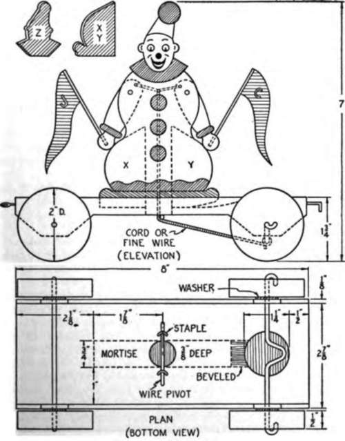
Fig. 3.1 1. Animated clown.
Because the rear wheels move the crank, this is a good example of a "fixed" axle. After the axle housings are attached and the crank has been shaped, one end of the axle is bent into a small half-circle and its end embedded in a minute hole in one wheel. Both of the thin washers are then slid into place on either side of the crank, and the axle is gently threaded through the holes in the housing. A little patience in measuring and bending the sharpened outer end of the wire axle toward the small hole near the hub, will be rewarded when fairly large-jawed pliers finish the job by straddling the inside of the housing and the outside of the wheel. The front wheels, being freewheeling, may be mounted on any convenient axle. Those shown in the diagram rotate on a J-in. dowel.
With the wheels in position the assembled clown is set in place and, when the crank is in the extreme right-hand position indicated in the plan, the thread is tentatively tied to it. The rear wheels are then turned to determine the'fit of the bevel and the proper length of the piece of thread, wire, cord, or line. After all adjustments have satisfactorily passed several trial spins, the figure is glued into its mortise, and a screweye and L-hook are inserted so that the bright-eyed clown can join the parade.
Continue to:
My Books

