Alternating Currents, Choking Coils, Transformers, Converters And Rectifiers. Part 2
Description
This section is from the book "Electricity For Boys. The "How-To-Do-It" Books", by J. S. Zerbe. Also available from Amazon: Electricity for Boys.
Alternating Currents, Choking Coils, Transformers, Converters And Rectifiers. Part 2
Current Reversing Itself
When the loop reaches its lowest point (Fig. 106) it again comes within the magnetic field and the current commences to flow back to its original direction, as shown by darts (C)
Self-Induction
This tendency of a current to reverse itself, under the conditions cited, is called self-induction, or inductance, and it would be well to keep this in mind in pursuing the study of alternating currents.
You will see from the foregoing, that the alternations, or the change of direction of the current, depends upon the speed of rotation of the loop past the end of the magnet.
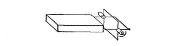 Fig. 107. Form for Increasing Alternations
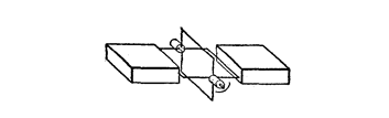 Fig. 108. Form for Increasing Alternations
Instead, therefore, of using a single loop, we may make four loops (Fig. 107), which at the same speed as we had in the case of the single loop, will give four alternations, instead of one, and still further, to increase the periods of alternation, we may use the four loops and two magnets, as in Fig. 108. By having a sufficient number of loops and of magnets, there may be 40, 50, 60, 80, 100 or 120 such alternating periods in each second. Time, therefore, is an element in the operation of alternating currents.
Let us now illustrate the manner of connecting up and building the dynamo, so as to derive the current from it. In Fig. 109, the loop (A) shows, for convenience, a pair of bearings (B). A contact finger (C) rests on each, and to these the circuit wire (D) is attached. Do not confuse these contact fingers with the commutator brushes, shown in the direct-current motor, as they are there merely for the purpose of making contact between the revolving loop (A) and stationary wire (D).
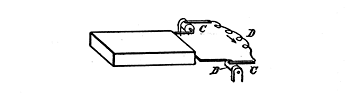 Fig. 109. Connection of Alternating Dynamo Armature
Brushes In A Direct-Current Dynamo
The object of the brushes in the direct-current dynamo, in connection with a commutator, is to convert this inductance of the wire, or this effort to reverse itself into a current which will go in one direction all the time, and not in both directions alternately.
To explain this more fully attention is directed to Figs. 110 and 111. Let A represent the armature, with a pair of grooves (B) for the wires. The commutator is made of a split tube, the parts so divided being insulated from each other, and in Fig. 110, the upper one, we shall call and designate the positive (+) and the lower one the negative (-). The armature wire (C) has one end attached to the positive commutator terminal and the other end of this wire is attached to the negative terminal.
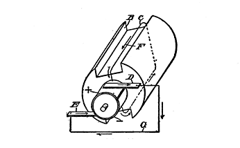 Fig. 110. Direct Current Dynamo
One brush (D) contacts with the positive terminal of the commutator and the other brush (E) with the negative terminal. Let us assume that the current impulse imparted to the wire (C) is in the direction of the dart (F, Fig. 110). The current will then flow through the positive (+) terminal of the commutator to the brush (D), and from the brush (D) through the wire (G) to the brush (E), which contacts with the negative (-) terminal of the commutator. This will continue to be the case, while the wire (C) is passing the magnetic field, and while the brush (D) is in contact with the positive (+) terminal. But when the armature makes a half turn, or when it reaches that point where the brush (D) contacts with the negative (-) terminal, and the brush (E) contacts with the positive (+) terminal, a change in the direction of the current through the wire (G) takes place, unless something has happened to change it before it has reached the brushes (D, E).
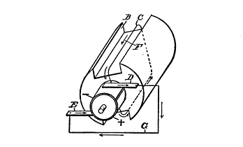 Fig. 111. Circuit Wires in Direct Current Dynamo
Now, this change is just exactly what has happened in the wire (C), as we have explained. The current attempts to reverse itself and start out on business of its own, so to speak, with the result that when the brushes (D and E) contact with the negative and positive terminals, respectively, the surging current in the wire (C) is going in the direction of the dart (H) - that is, while, in Fig. 110, the current flows from the wire (C) into the positive terminal, and out of the negative terminal into the wire (C), the conditions are exactly reversed in Fig. 111. Here the current in wire C flows into the negative (-) terminal, and from the positive (+) terminal into the wire C, so that in either case the current will flow out of the brush D and into the brush E, through the external circuit (G).
It will be seen, therefore, that in the direct-current motor, advantage is taken of the surging, or back-and-forth movement, of the current to pass it along in one direction, whereas in the alternating current no such change in direction is attempted.
Continue to:
My Books

